
Conveyor components are selected around chain, load and environment
Plastic sprockets and functional molded parts are widely considered where corrosion, noise, weight or product contact makes engineering plastics attractive. The correct choice depends on the chain series, tooth count, shaft interface, conveyed load, speed and contamination or washdown conditions.
For a replacement sprocket, provide the chain designation and the existing bore/hub geometry. For a new conveyor, include shaft spacing, chain layout and the expected operating duty.

Conveyor RFQ inputs
- Chain series or exact chain dimensions
- Tooth count and sprocket pitch diameter requirements
- Bore, keyway, set-screw or hub interface
- Single or multiple-strand layout
- Load, speed, duty cycle and cleaning environment
- Required interchangeability with an existing part
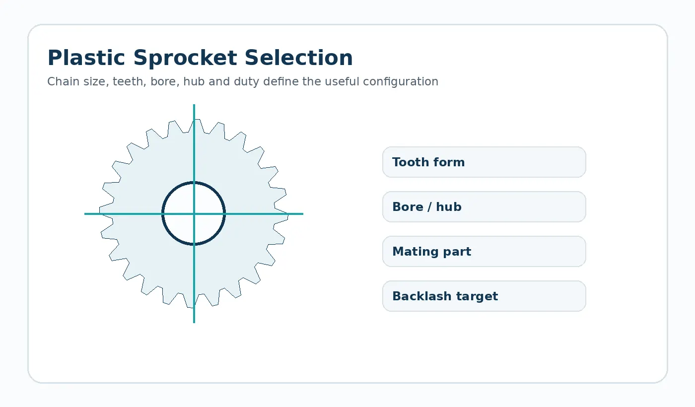
Chain and shaft alignment set the baseline
A plastic sprocket cannot compensate indefinitely for an elongated chain or shafts that are not parallel. Before changing material, inspect chain condition, guide alignment and tensioning method. Side wear concentrated on one face is often a sign that the chain path itself needs attention.
For new conveyor layouts, specify strand count and how the sprockets are located laterally on the shaft. Multi-strand systems need consistent spacing across the drive and idler positions.

Environment changes polymer selection
Washdown water, detergents, abrasive dust or elevated product temperature can alter the preferred material. A resin that performs well in a clean dry conveyor may not be appropriate in a chemically cleaned line.
Describe the exposure and cleaning schedule in the RFQ. If the component contacts product or packaging directly, state any applicable material or regulatory requirement rather than assuming it from the application name.
Replacement sprocket information
- Chain manufacturer/series or verified chain dimensions
- Tooth count and strand arrangement
- Bore, keyway, set-screw and hub geometry
- Shaft spacing and tensioning method
- Existing wear pattern or failure mode
- Cleaning, contamination and operating temperature
此应用程序的验证计划
首件检验应围绕机床接口展开。确认安装基准、配合部件或链条、预期载荷方向、典型转速/循环模式以及运行环境。如果位置或间隙至关重要,则应在经过典型调校和循环后测量装配后的机构,而不仅仅是批准自由部件。
务必记录下零件图纸上容易被忽略的任何现场限制因素:例如防护罩间隙、清洗化学品、电机附近发热、无支撑齿条跨距、反转工况或固定齿轮中心的轴承布置。这些细节通常可以解释为什么尺寸符合要求的零件在实际使用中表现不同。
Application acceptance rail
Before release, tie the component back to four controls: the operating duty, the mating interface, the environmental condition used for dimensional acceptance and the functional test that represents the real assembly. These controls prevent a nominally correct part from being approved under conditions that do not match service.
Duty
Peak and normal load, speed, reversals, cycle profile and expected service interval.
Interface
Mating geometry, support, alignment, fastener or shaft fit and the datum scheme used for measurement.
Acceptance
Conditioning state, critical dimensions, visual criteria and an assembly or motion check agreed before repeat production.
Information to include in the application review
Document the complete operating envelope rather than only nominal speed or load. Include starts and reversals, worst-case temperature and moisture, cleaning chemicals or lubricants, shaft and bearing support, the mating material, available installation space and any field-replacement constraint. If noise, backlash, wear or positional repeatability is the reason for the project, state that explicitly so the drawing and inspection plan can focus on the real problem.
For first samples, define what will be checked in the component and what will be checked in the machine. A dimensional report verifies the drawing; an assembly or functional test verifies that the selected datums, fits and material condition produce the required behavior. Both are useful when the mechanism is sensitive to cumulative tolerances.

























