
Conveyor components are selected around chain, load and environment
Plastic sprockets and functional molded parts are widely considered where corrosion, noise, weight or product contact makes engineering plastics attractive. The correct choice depends on the chain series, tooth count, shaft interface, conveyed load, speed and contamination or washdown conditions.
For a replacement sprocket, provide the chain designation and the existing bore/hub geometry. For a new conveyor, include shaft spacing, chain layout and the expected operating duty.

Conveyor RFQ inputs
- Chain series or exact chain dimensions
- Tooth count and sprocket pitch diameter requirements
- Bore, keyway, set-screw or hub interface
- Single or multiple-strand layout
- Load, speed, duty cycle and cleaning environment
- Required interchangeability with an existing part
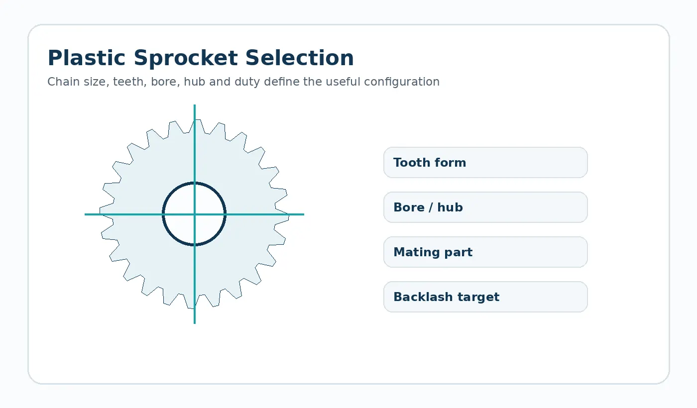
Chain and shaft alignment set the baseline
A plastic sprocket cannot compensate indefinitely for an elongated chain or shafts that are not parallel. Before changing material, inspect chain condition, guide alignment and tensioning method. Side wear concentrated on one face is often a sign that the chain path itself needs attention.
For new conveyor layouts, specify strand count and how the sprockets are located laterally on the shaft. Multi-strand systems need consistent spacing across the drive and idler positions.

Environment changes polymer selection
Washdown water, detergents, abrasive dust or elevated product temperature can alter the preferred material. A resin that performs well in a clean dry conveyor may not be appropriate in a chemically cleaned line.
Describe the exposure and cleaning schedule in the RFQ. If the component contacts product or packaging directly, state any applicable material or regulatory requirement rather than assuming it from the application name.
Replacement sprocket information
- Chain manufacturer/series or verified chain dimensions
- Tooth count and strand arrangement
- Bore, keyway, set-screw and hub geometry
- Shaft spacing and tensioning method
- Existing wear pattern or failure mode
- Cleaning, contamination and operating temperature
이 애플리케이션에 대한 검증 계획
기계 인터페이스를 중심으로 초기 샘플 검사를 수행하십시오. 장착 기준점, 결합 부품 또는 체인, 예상 하중 방향, 대표적인 속도/사이클 패턴 및 사용 환경을 확인하십시오. 위치 또는 백래시가 중요한 경우, 단순히 자유로운 부품만 승인하는 것이 아니라 대표적인 조건 및 사이클링 후 조립된 메커니즘을 측정하십시오.
부품 도면에서 간과하기 쉬운 현장 제약 조건(예: 가드 간극, 세척제, 인근 모터 열, 지지되지 않은 랙 간격, 역회전 작동, 기어 중심을 고정하는 베어링 배열 등)을 문서화하십시오. 이러한 세부 사항은 치수적으로는 문제가 없는 부품이 실제 사용 환경에서 다르게 작동하는 이유를 설명하는 데 도움이 될 수 있습니다.
신청 승인 레일
출고 전에 부품을 다음 네 가지 기준에 맞춰 검증해야 합니다. 작동 조건, 결합 인터페이스, 치수 허용 오차에 사용되는 환경 조건, 그리고 실제 조립 상태를 재현하는 기능 테스트입니다. 이러한 검증을 통해 명목상 올바른 부품이라도 실제 사용 환경과 일치하지 않는 조건에서 승인되는 것을 방지할 수 있습니다.
의무
최대 부하 및 정상 부하, 속도, 역회전, 사이클 프로파일 및 예상 서비스 간격.
인터페이스
결합 형상, 지지대, 정렬, 체결 부품 또는 축 맞춤 및 측정에 사용되는 기준 체계.
수락
반복 생산 전에 조건 상태, 중요 치수, 시각적 기준 및 조립 또는 동작 검사에 대한 합의가 이루어져야 합니다.

























