
Conveyor components are selected around chain, load and environment
Plastic sprockets and functional molded parts are widely considered where corrosion, noise, weight or product contact makes engineering plastics attractive. The correct choice depends on the chain series, tooth count, shaft interface, conveyed load, speed and contamination or washdown conditions.
For a replacement sprocket, provide the chain designation and the existing bore/hub geometry. For a new conveyor, include shaft spacing, chain layout and the expected operating duty.

Conveyor RFQ inputs
- Chain series or exact chain dimensions
- Tooth count and sprocket pitch diameter requirements
- Bore, keyway, set-screw or hub interface
- Single or multiple-strand layout
- Load, speed, duty cycle and cleaning environment
- Required interchangeability with an existing part
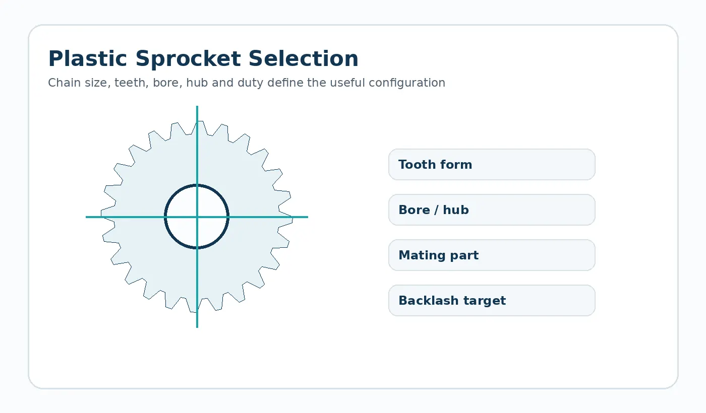
Chain and shaft alignment set the baseline
A plastic sprocket cannot compensate indefinitely for an elongated chain or shafts that are not parallel. Before changing material, inspect chain condition, guide alignment and tensioning method. Side wear concentrated on one face is often a sign that the chain path itself needs attention.
For new conveyor layouts, specify strand count and how the sprockets are located laterally on the shaft. Multi-strand systems need consistent spacing across the drive and idler positions.

Environment changes polymer selection
Washdown water, detergents, abrasive dust or elevated product temperature can alter the preferred material. A resin that performs well in a clean dry conveyor may not be appropriate in a chemically cleaned line.
Describe the exposure and cleaning schedule in the RFQ. If the component contacts product or packaging directly, state any applicable material or regulatory requirement rather than assuming it from the application name.
Replacement sprocket information
- Chain manufacturer/series or verified chain dimensions
- Tooth count and strand arrangement
- Bore, keyway, set-screw and hub geometry
- Shaft spacing and tensioning method
- Existing wear pattern or failure mode
- Cleaning, contamination and operating temperature
Validation plan for this application
Build the first-sample check around the machine interface. Confirm the mounting datums, mating part or chain, expected load direction, representative speed/cycle pattern and the service environment. Where position or backlash matters, measure the assembled mechanism after representative conditioning and cycling rather than approving only the free component.
Document any field constraint that is easy to miss on a component drawing: guard clearance, washdown chemical, nearby motor heat, unsupported rack span, reversing duty, or the bearing arrangement that fixes gear centers. These details often explain why a dimensionally acceptable part behaves differently in service.
Application acceptance rail
Before release, tie the component back to four controls: the operating duty, the mating interface, the environmental condition used for dimensional acceptance and the functional test that represents the real assembly. These controls prevent a nominally correct part from being approved under conditions that do not match service.
Duty
Peak and normal load, speed, reversals, cycle profile and expected service interval.
Interface
Mating geometry, support, alignment, fastener or shaft fit and the datum scheme used for measurement.
Acceptance
Conditioning state, critical dimensions, visual criteria and an assembly or motion check agreed before repeat production.
Information to include in the application review
Document the complete operating envelope rather than only nominal speed or load. Include starts and reversals, worst-case temperature and moisture, cleaning chemicals or lubricants, shaft and bearing support, the mating material, available installation space and any field-replacement constraint. If noise, backlash, wear or positional repeatability is the reason for the project, state that explicitly so the drawing and inspection plan can focus on the real problem.
For first samples, define what will be checked in the component and what will be checked in the machine. A dimensional report verifies the drawing; an assembly or functional test verifies that the selected datums, fits and material condition produce the required behavior. Both are useful when the mechanism is sensitive to cumulative tolerances.

























