
Conveyor components are selected around chain, load and environment
Plastic sprockets and functional molded parts are widely considered where corrosion, noise, weight or product contact makes engineering plastics attractive. The correct choice depends on the chain series, tooth count, shaft interface, conveyed load, speed and contamination or washdown conditions.
For a replacement sprocket, provide the chain designation and the existing bore/hub geometry. For a new conveyor, include shaft spacing, chain layout and the expected operating duty.

Conveyor RFQ inputs
- Chain series or exact chain dimensions
- Tooth count and sprocket pitch diameter requirements
- Bore, keyway, set-screw or hub interface
- Single or multiple-strand layout
- Load, speed, duty cycle and cleaning environment
- Required interchangeability with an existing part
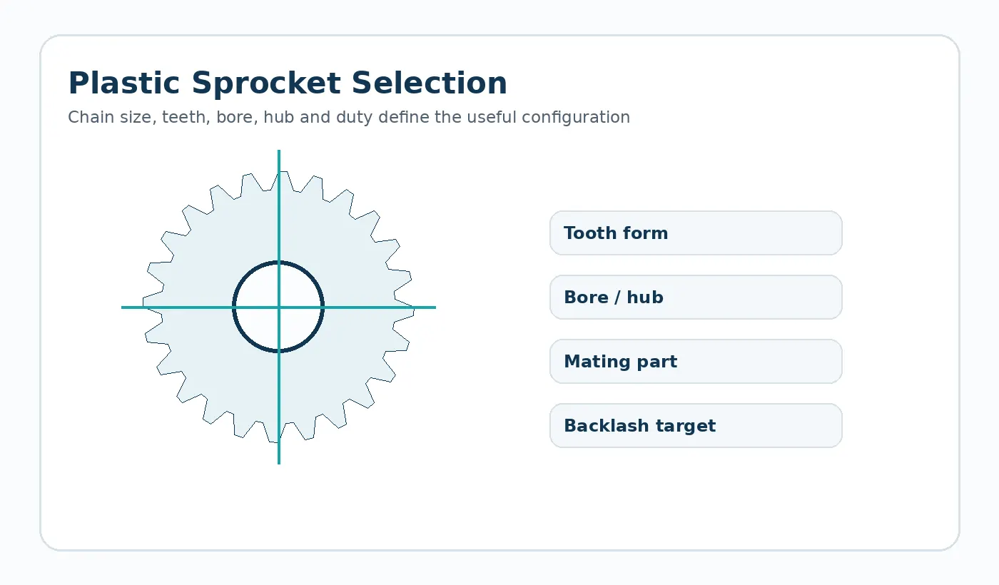
Chain and shaft alignment set the baseline
A plastic sprocket cannot compensate indefinitely for an elongated chain or shafts that are not parallel. Before changing material, inspect chain condition, guide alignment and tensioning method. Side wear concentrated on one face is often a sign that the chain path itself needs attention.
For new conveyor layouts, specify strand count and how the sprockets are located laterally on the shaft. Multi-strand systems need consistent spacing across the drive and idler positions.

Environment changes polymer selection
Washdown water, detergents, abrasive dust or elevated product temperature can alter the preferred material. A resin that performs well in a clean dry conveyor may not be appropriate in a chemically cleaned line.
Describe the exposure and cleaning schedule in the RFQ. If the component contacts product or packaging directly, state any applicable material or regulatory requirement rather than assuming it from the application name.
Replacement sprocket information
- Chain manufacturer/series or verified chain dimensions
- Tooth count and strand arrangement
- Bore, keyway, set-screw and hub geometry
- Shaft spacing and tensioning method
- Existing wear pattern or failure mode
- Cleaning, contamination and operating temperature
Plano de validação para esta aplicação
Construa a verificação da primeira amostra em torno da interface da máquina. Confirme os pontos de referência de montagem, a peça ou corrente de acoplamento, a direção esperada da carga, o padrão representativo de velocidade/ciclo e o ambiente de serviço. Quando a posição ou a folga forem importantes, meça o mecanismo montado após condicionamento e ciclos representativos, em vez de aprovar apenas o componente solto.
Documente qualquer restrição de campo que seja fácil de passar despercebida em um desenho de componente: folga da proteção, produto químico de lavagem, calor do motor próximo, vão da cremalheira sem suporte, operação em marcha à ré ou o arranjo dos rolamentos que fixa os centros das engrenagens. Esses detalhes geralmente explicam por que uma peça dimensionalmente aceitável se comporta de maneira diferente em serviço.
Trilho de aceitação de aplicação
Antes da liberação, vincule o componente a quatro controles: a condição operacional, a interface de acoplamento, a condição ambiental utilizada para a aceitação dimensional e o teste funcional que representa a montagem real. Esses controles impedem que uma peça nominalmente correta seja aprovada em condições que não correspondam ao serviço.
Obrigação
Carga máxima e normal, velocidade, inversões, perfil do ciclo e intervalo de manutenção previsto.
Interface
Geometria de acoplamento, suporte, alinhamento, encaixe do fixador ou eixo e o sistema de referência utilizado para a medição.
Aceitação
O estado de condicionamento, as dimensões críticas, os critérios visuais e a verificação de montagem ou movimento são acordados antes da produção repetida.
Information to include in the application review
Document the complete operating envelope rather than only nominal speed or load. Include starts and reversals, worst-case temperature and moisture, cleaning chemicals or lubricants, shaft and bearing support, the mating material, available installation space and any field-replacement constraint. If noise, backlash, wear or positional repeatability is the reason for the project, state that explicitly so the drawing and inspection plan can focus on the real problem.
For first samples, define what will be checked in the component and what will be checked in the machine. A dimensional report verifies the drawing; an assembly or functional test verifies that the selected datums, fits and material condition produce the required behavior. Both are useful when the mechanism is sensitive to cumulative tolerances.

























