
Packaging machines reward controlled low-mass motion
Packaging equipment can place gears, racks, sprockets and molded guides close to product flow, film paths, sealing mechanisms and repeated indexing stations. Fast cycling makes alignment, wear and dimensional consistency more important than a simple material label.
Specify the drive ratio, shaft or rack interface, cleaning conditions and expected maintenance approach before selecting a component family.

Packaging-machine selection priorities
Indexing and timing
Confirm cycle rate, acceleration, driven inertia and allowable lost motion.
Cleanability
Describe washdown, food-zone restrictions or chemical exposure when applicable.
Maintenance
Consider access, lubrication strategy, replacement interval and compatibility with mating components.
Duty cycle matters more than average speed
Packaging machinery often accelerates and decelerates parts repeatedly. The peak tooth load during indexing can differ significantly from a simple average-torque estimate. Include jams, emergency stops or start-up transients when they are credible service events.
If the gear or rack is close to a product-contact zone, material and lubricant restrictions may narrow the design. Cleanability and chemical exposure should be described rather than assumed from the word “packaging.”
Noise, wear and timing are linked
Changing to a plastic gear can reduce transmitted noise in some mechanisms, but noise is also affected by runout, center distance and tooth contact. A quiet first sample is not enough if the gear wears quickly under the full cycle profile.
Run representative cycling and inspect tooth wear, backlash and shaft/bearing condition together. This helps distinguish a material issue from an alignment or support issue.
Useful RFQ details
- Machine function and cycle rate
- Gear/rack ratio and complete mating geometry
- Permitted lubricant and cleaning chemicals
- Temperature near heaters, sealers or motors
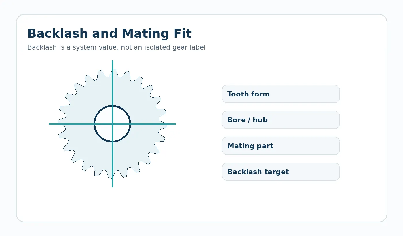
- Required timing/backlash behavior
- Replacement envelope or interchangeability constraints
Plano de validação para esta aplicação
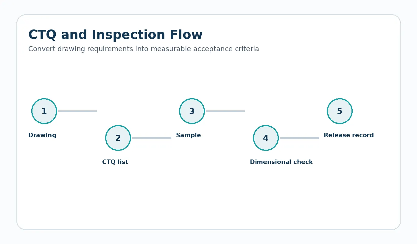
Construa a verificação da primeira amostra em torno da interface da máquina. Confirme os pontos de referência de montagem, a peça ou corrente de acoplamento, a direção esperada da carga, o padrão representativo de velocidade/ciclo e o ambiente de serviço. Quando a posição ou a folga forem importantes, meça o mecanismo montado após condicionamento e ciclos representativos, em vez de aprovar apenas o componente solto.
Documente qualquer restrição de campo que seja fácil de passar despercebida em um desenho de componente: folga da proteção, produto químico de lavagem, calor do motor próximo, vão da cremalheira sem suporte, operação em marcha à ré ou o arranjo dos rolamentos que fixa os centros das engrenagens. Esses detalhes geralmente explicam por que uma peça dimensionalmente aceitável se comporta de maneira diferente em serviço.
Trilho de aceitação de aplicação
Antes da liberação, vincule o componente a quatro controles: a condição operacional, a interface de acoplamento, a condição ambiental utilizada para a aceitação dimensional e o teste funcional que representa a montagem real. Esses controles impedem que uma peça nominalmente correta seja aprovada em condições que não correspondam ao serviço.
Obrigação
Carga máxima e normal, velocidade, inversões, perfil do ciclo e intervalo de manutenção previsto.
Interface
Geometria de acoplamento, suporte, alinhamento, encaixe do fixador ou eixo e o sistema de referência utilizado para a medição.
Aceitação
O estado de condicionamento, as dimensões críticas, os critérios visuais e a verificação de montagem ou movimento são acordados antes da produção repetida.
Information to include in the application review
Document the complete operating envelope rather than only nominal speed or load. Include starts and reversals, worst-case temperature and moisture, cleaning chemicals or lubricants, shaft and bearing support, the mating material, available installation space and any field-replacement constraint. If noise, backlash, wear or positional repeatability is the reason for the project, state that explicitly so the drawing and inspection plan can focus on the real problem.
For first samples, define what will be checked in the component and what will be checked in the machine. A dimensional report verifies the drawing; an assembly or functional test verifies that the selected datums, fits and material condition produce the required behavior. Both are useful when the mechanism is sensitive to cumulative tolerances.

























