
Packaging machines reward controlled low-mass motion
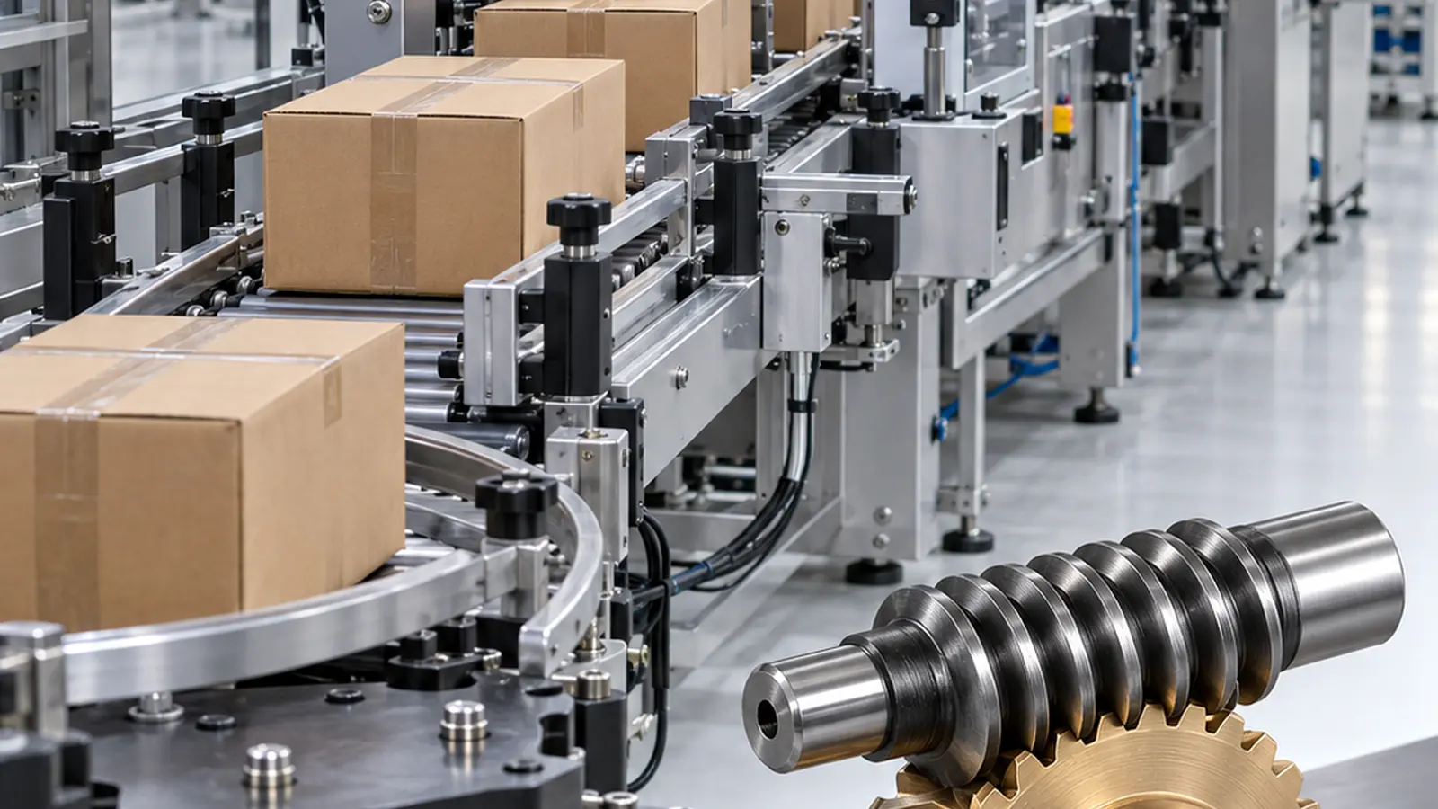
Packaging equipment can place gears, racks, sprockets and molded guides close to product flow, film paths, sealing mechanisms and repeated indexing stations. Fast cycling makes alignment, wear and dimensional consistency more important than a simple material label.
Specify the drive ratio, shaft or rack interface, cleaning conditions and expected maintenance approach before selecting a component family.
Packaging-machine selection priorities
Indexing and timing
Confirm cycle rate, acceleration, driven inertia and allowable lost motion.
Cleanability
Describe washdown, food-zone restrictions or chemical exposure when applicable.
Maintenance
Consider access, lubrication strategy, replacement interval and compatibility with mating components.
Duty cycle matters more than average speed
Packaging machinery often accelerates and decelerates parts repeatedly. The peak tooth load during indexing can differ significantly from a simple average-torque estimate. Include jams, emergency stops or start-up transients when they are credible service events.
If the gear or rack is close to a product-contact zone, material and lubricant restrictions may narrow the design. Cleanability and chemical exposure should be described rather than assumed from the word “packaging.”
Noise, wear and timing are linked
Changing to a plastic gear can reduce transmitted noise in some mechanisms, but noise is also affected by runout, center distance and tooth contact. A quiet first sample is not enough if the gear wears quickly under the full cycle profile.
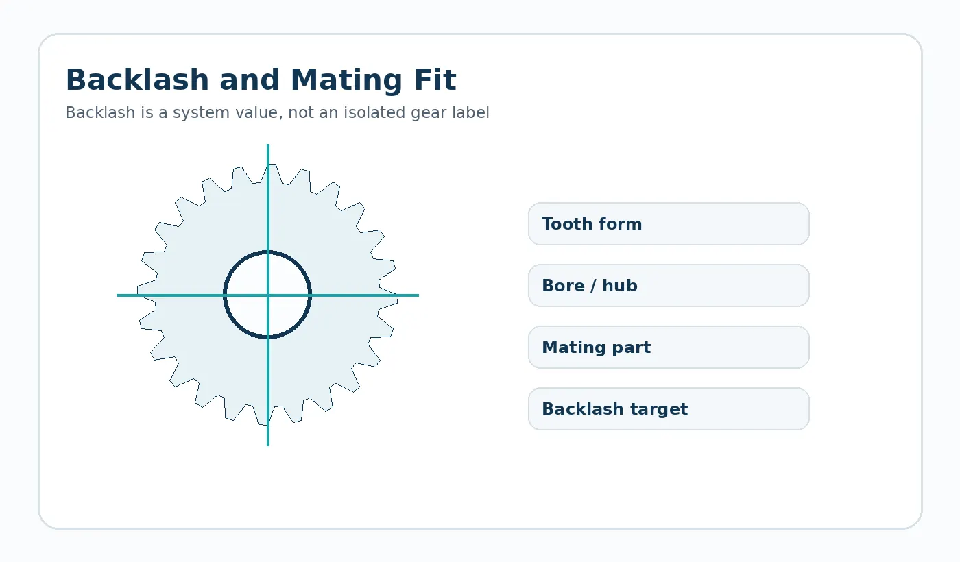
Run representative cycling and inspect tooth wear, backlash and shaft/bearing condition together. This helps distinguish a material issue from an alignment or support issue.
Useful RFQ details
- Machine function and cycle rate
- Gear/rack ratio and complete mating geometry
- Permitted lubricant and cleaning chemicals
- Temperature near heaters, sealers or motors
- Required timing/backlash behavior
- Replacement envelope or interchangeability constraints
이 애플리케이션에 대한 검증 계획
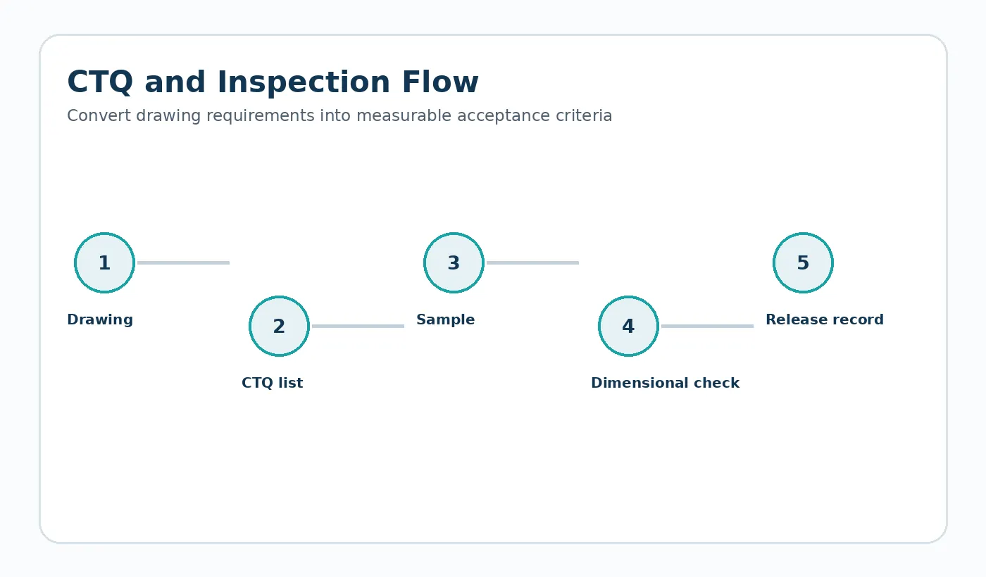
기계 인터페이스를 중심으로 초기 샘플 검사를 수행하십시오. 장착 기준점, 결합 부품 또는 체인, 예상 하중 방향, 대표적인 속도/사이클 패턴 및 사용 환경을 확인하십시오. 위치 또는 백래시가 중요한 경우, 단순히 자유로운 부품만 승인하는 것이 아니라 대표적인 조건 및 사이클링 후 조립된 메커니즘을 측정하십시오.
부품 도면에서 간과하기 쉬운 현장 제약 조건(예: 가드 간극, 세척제, 인근 모터 열, 지지되지 않은 랙 간격, 역회전 작동, 기어 중심을 고정하는 베어링 배열 등)을 문서화하십시오. 이러한 세부 사항은 치수적으로는 문제가 없는 부품이 실제 사용 환경에서 다르게 작동하는 이유를 설명하는 데 도움이 될 수 있습니다.
신청 승인 레일
출고 전에 부품을 다음 네 가지 기준에 맞춰 검증해야 합니다. 작동 조건, 결합 인터페이스, 치수 허용 오차에 사용되는 환경 조건, 그리고 실제 조립 상태를 재현하는 기능 테스트입니다. 이러한 검증을 통해 명목상 올바른 부품이라도 실제 사용 환경과 일치하지 않는 조건에서 승인되는 것을 방지할 수 있습니다.
의무
최대 부하 및 정상 부하, 속도, 역회전, 사이클 프로파일 및 예상 서비스 간격.
인터페이스
결합 형상, 지지대, 정렬, 체결 부품 또는 축 맞춤 및 측정에 사용되는 기준 체계.
수락
반복 생산 전에 조건 상태, 중요 치수, 시각적 기준 및 조립 또는 동작 검사에 대한 합의가 이루어져야 합니다.
Information to include in the application review
Document the complete operating envelope rather than only nominal speed or load. Include starts and reversals, worst-case temperature and moisture, cleaning chemicals or lubricants, shaft and bearing support, the mating material, available installation space and any field-replacement constraint. If noise, backlash, wear or positional repeatability is the reason for the project, state that explicitly so the drawing and inspection plan can focus on the real problem.
For first samples, define what will be checked in the component and what will be checked in the machine. A dimensional report verifies the drawing; an assembly or functional test verifies that the selected datums, fits and material condition produce the required behavior. Both are useful when the mechanism is sensitive to cumulative tolerances.

























