
Packaging machines reward controlled low-mass motion
Packaging equipment can place gears, racks, sprockets and molded guides close to product flow, film paths, sealing mechanisms and repeated indexing stations. Fast cycling makes alignment, wear and dimensional consistency more important than a simple material label.
Specify the drive ratio, shaft or rack interface, cleaning conditions and expected maintenance approach before selecting a component family.

Packaging-machine selection priorities
Indexing and timing
Confirm cycle rate, acceleration, driven inertia and allowable lost motion.
Cleanability
Describe washdown, food-zone restrictions or chemical exposure when applicable.
Maintenance
Consider access, lubrication strategy, replacement interval and compatibility with mating components.
Duty cycle matters more than average speed
Packaging machinery often accelerates and decelerates parts repeatedly. The peak tooth load during indexing can differ significantly from a simple average-torque estimate. Include jams, emergency stops or start-up transients when they are credible service events.
If the gear or rack is close to a product-contact zone, material and lubricant restrictions may narrow the design. Cleanability and chemical exposure should be described rather than assumed from the word “packaging.”
Noise, wear and timing are linked
Changing to a plastic gear can reduce transmitted noise in some mechanisms, but noise is also affected by runout, center distance and tooth contact. A quiet first sample is not enough if the gear wears quickly under the full cycle profile.
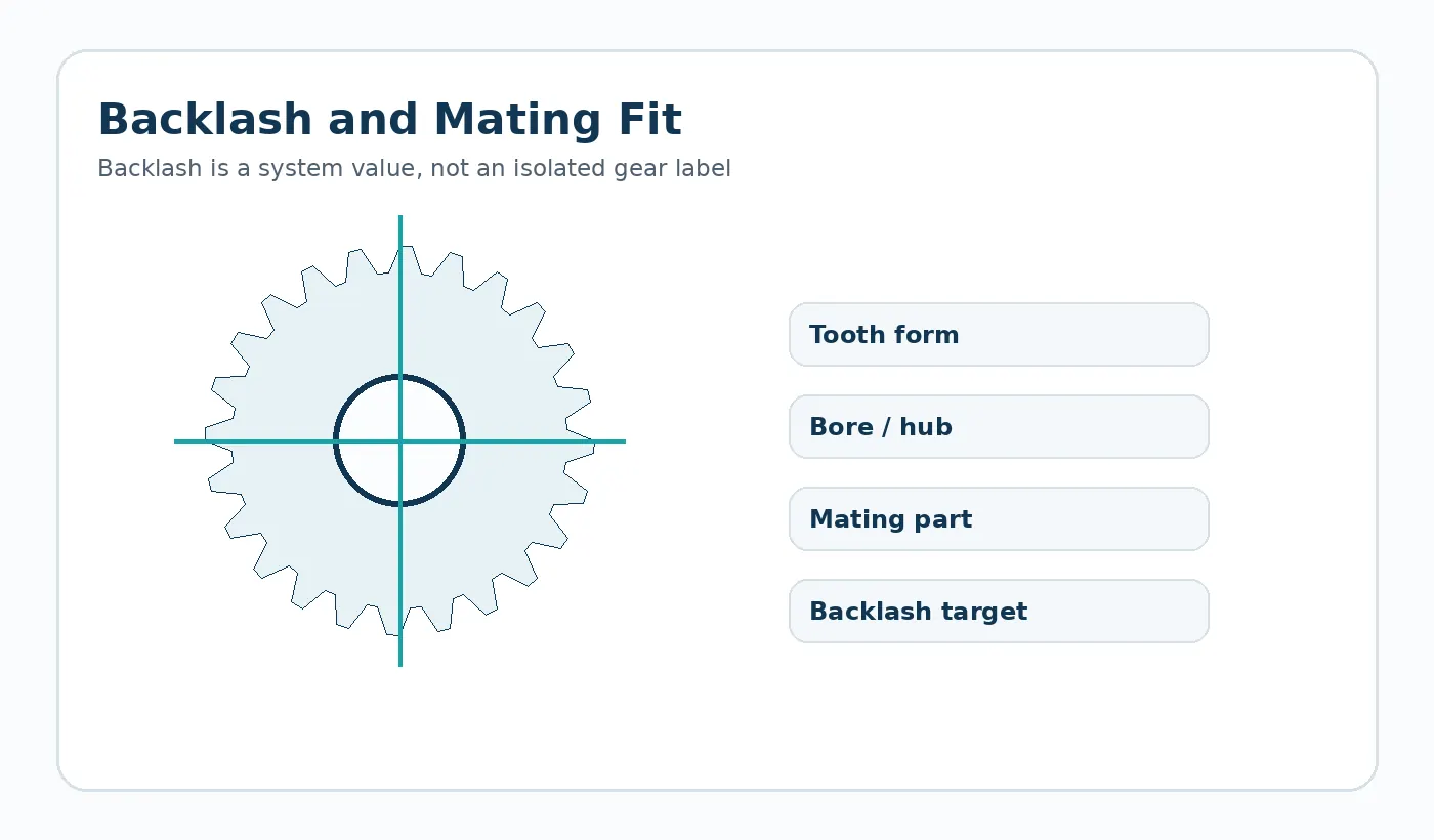
Run representative cycling and inspect tooth wear, backlash and shaft/bearing condition together. This helps distinguish a material issue from an alignment or support issue.
Useful RFQ details
- Machine function and cycle rate
- Gear/rack ratio and complete mating geometry
- Permitted lubricant and cleaning chemicals
- Temperature near heaters, sealers or motors
- Required timing/backlash behavior
- Replacement envelope or interchangeability constraints
Validation plan for this application
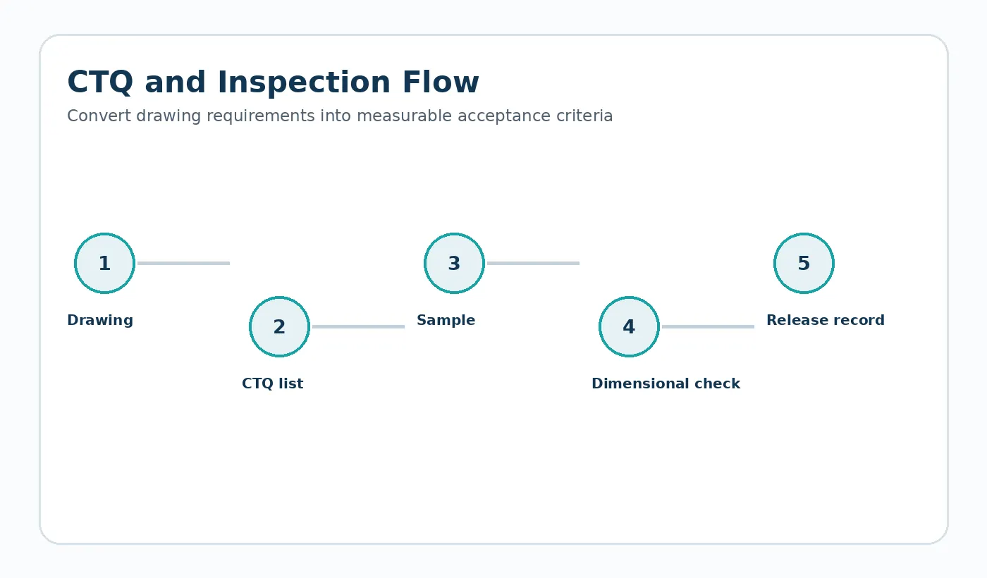
Build the first-sample check around the machine interface. Confirm the mounting datums, mating part or chain, expected load direction, representative speed/cycle pattern and the service environment. Where position or backlash matters, measure the assembled mechanism after representative conditioning and cycling rather than approving only the free component.
Document any field constraint that is easy to miss on a component drawing: guard clearance, washdown chemical, nearby motor heat, unsupported rack span, reversing duty, or the bearing arrangement that fixes gear centers. These details often explain why a dimensionally acceptable part behaves differently in service.
Application acceptance rail
Before release, tie the component back to four controls: the operating duty, the mating interface, the environmental condition used for dimensional acceptance and the functional test that represents the real assembly. These controls prevent a nominally correct part from being approved under conditions that do not match service.
Duty
Peak and normal load, speed, reversals, cycle profile and expected service interval.
Interface
Mating geometry, support, alignment, fastener or shaft fit and the datum scheme used for measurement.
Acceptance
Conditioning state, critical dimensions, visual criteria and an assembly or motion check agreed before repeat production.
Information to include in the application review
Document the complete operating envelope rather than only nominal speed or load. Include starts and reversals, worst-case temperature and moisture, cleaning chemicals or lubricants, shaft and bearing support, the mating material, available installation space and any field-replacement constraint. If noise, backlash, wear or positional repeatability is the reason for the project, state that explicitly so the drawing and inspection plan can focus on the real problem.
For first samples, define what will be checked in the component and what will be checked in the machine. A dimensional report verifies the drawing; an assembly or functional test verifies that the selected datums, fits and material condition produce the required behavior. Both are useful when the mechanism is sensitive to cumulative tolerances.

























