
Plastic components in automated mechanisms
Industrial automation often combines repetitive motion, compact packaging and short cycle times. Plastic gears, racks and molded guides can reduce mass and simplify component integration, but the selection still depends on load, speed, support stiffness, backlash sensitivity and the environment around the machine.
For indexing or positioning mechanisms, share the complete motion path and the mating drive geometry rather than specifying one gear in isolation.

What to define for automation duty
Cycle profile
Continuous rotation, indexing, reversals and dwell periods affect heat and wear.
Positioning requirement
Backlash, compliance and assembly tolerances can influence repeatability.
Machine environment
Dust, lubricants, cleaning agents and ambient temperature may change material choice.
Indexing, reversals and positioning
Automated equipment can reverse direction frequently, which makes backlash, shaft support and gear compliance visible as lost motion. An acceptable steady-running gear pair may behave differently during rapid accelerations or repeated indexing.
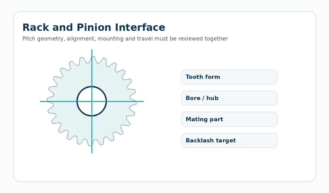
For rack-and-pinion axes, include rack support and pinion center-height adjustment. For compound or planetary sets, include the bearing and carrier geometry that fixes the relative gear centers.
Material choice inside an automation cell
Oil mist, coolant, dust, washdown fluid and local heat from motors can be more important than the nominal room environment. If a polymer is expected to run without lubrication, that requirement should be stated together with the mating material and surface condition.
When positioning is critical, validate the complete mechanism over the expected temperature range and after representative cycling rather than approving only the free gear dimensions.
Automation RFQ package
- Motion profile: speed, reversals, dwell and cycle rate
- Torque/load and driven inertia
- Backlash or positioning target
- Mating gears, shafts, bearings and housing geometry
- Temperature, contaminants and lubricant condition
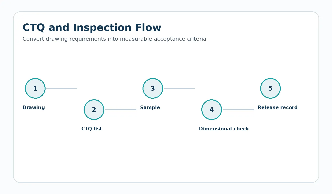
- Sample acceptance test in the machine or representative fixture
此应用程序的验证计划
首件检验应围绕机床接口展开。确认安装基准、配合部件或链条、预期载荷方向、典型转速/循环模式以及运行环境。如果位置或间隙至关重要,则应在经过典型调校和循环后测量装配后的机构,而不仅仅是批准自由部件。
务必记录下零件图纸上容易被忽略的任何现场限制因素:例如防护罩间隙、清洗化学品、电机附近发热、无支撑齿条跨距、反转工况或固定齿轮中心的轴承布置。这些细节通常可以解释为什么尺寸符合要求的零件在实际使用中表现不同。
Application acceptance rail
Before release, tie the component back to four controls: the operating duty, the mating interface, the environmental condition used for dimensional acceptance and the functional test that represents the real assembly. These controls prevent a nominally correct part from being approved under conditions that do not match service.
Duty
Peak and normal load, speed, reversals, cycle profile and expected service interval.
Interface
Mating geometry, support, alignment, fastener or shaft fit and the datum scheme used for measurement.
Acceptance
Conditioning state, critical dimensions, visual criteria and an assembly or motion check agreed before repeat production.
Information to include in the application review
Document the complete operating envelope rather than only nominal speed or load. Include starts and reversals, worst-case temperature and moisture, cleaning chemicals or lubricants, shaft and bearing support, the mating material, available installation space and any field-replacement constraint. If noise, backlash, wear or positional repeatability is the reason for the project, state that explicitly so the drawing and inspection plan can focus on the real problem.
For first samples, define what will be checked in the component and what will be checked in the machine. A dimensional report verifies the drawing; an assembly or functional test verifies that the selected datums, fits and material condition produce the required behavior. Both are useful when the mechanism is sensitive to cumulative tolerances.

























