
What changes the engineering choice
Glass-fibre reinforcement can increase stiffness, but it also changes molding behavior and the way the part interacts with mating surfaces.
Fibre orientation, gate location and wall flow can create direction-dependent shrinkage. Reinforced materials may also be more abrasive to mating components.
Fibre orientation follows mold flow, so the same nominal resin can shrink differently along different directions in the part. A gate change can therefore change flatness or hole location without changing the CAD. Reinforcement can also make a housing stiffer while increasing wear on sliding metal or plastic counterparts. Review both structural benefit and interface abrasion before selecting the grade.
Drawing and application data
Specify the grade, stiffness requirement, heat exposure, inserts/fasteners, surface finish and any wear interfaces.
Put these inputs on the controlled drawing, specification or RFQ attachment where possible. Keeping them out of informal message threads makes supplier comparisons and later revisions easier to manage.
A common source of error
Treating reinforced resin as a drop-in replacement for unfilled plastic can change dimensions and tool wear requirements.
How to prove the design
Validate critical flatness, hole position and assembly loads in the molded orientation of the production part.
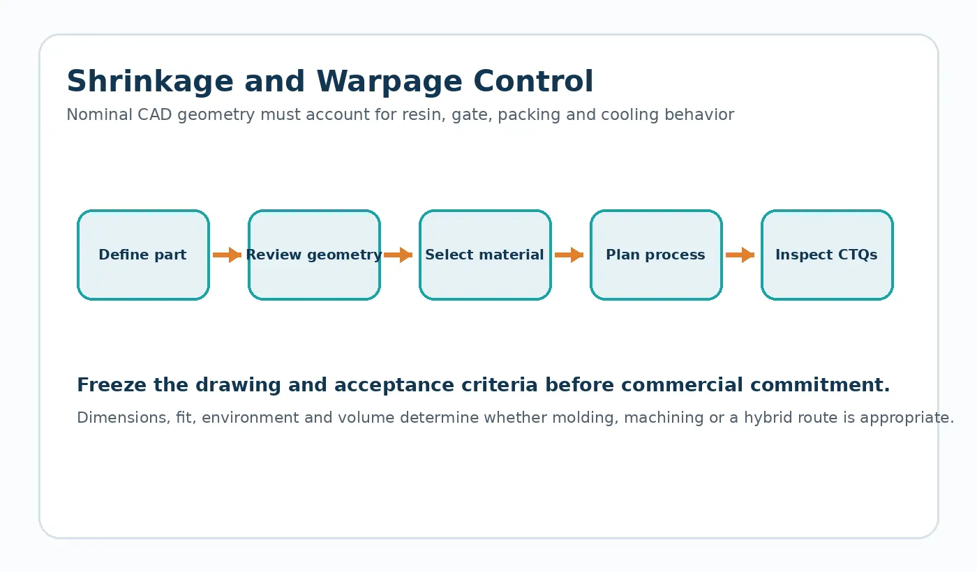
For Glass-Fibre-Reinforced Plastic Housing Design, close the DFM loop by updating the controlled CAD/drawing and sample plan. A recommendation that never reaches the released revision cannot be inspected consistently in production.

Supplier brief
Before requesting a price for glass-fibre-reinforced plastic housing design, identify the current drawing revision, production quantity, material constraint and the feature that most strongly affects function. Ask the supplier to flag any deviation from those inputs in the quotation so technical alternatives stay visible.
Practical design review for this decision
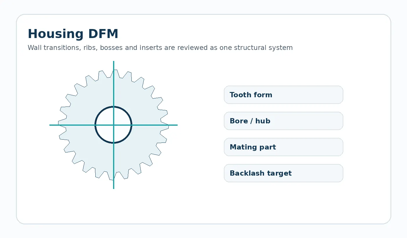
Housing DFM starts with a functional wall map. Keep wall transitions deliberate, use ribs and bosses to carry defined loads, provide draft where the tool needs release, and consider how gate and ejection locations interact with cosmetic and dimensional surfaces. The supplier should review these decisions against the selected resin and tool layout.
Record the assumptions on the drawing or RFQ so the supplier can confirm them before quoting. When a value is unknown, identify it as an open engineering item rather than copying a generic catalogue number that may not match the assembly.
Verification worksheet
- Nominal wall and transitions
- Rib/boss load path
- Draft and undercuts
- Insert / fastener loads
- Gate / parting / ejector restrictions
- Flatness and critical datums
Use the first sample to close these points with both dimensional evidence and the relevant functional check. Any accepted deviation should be captured in the controlled revision before repeat production.

























