
What changes the engineering choice
Glass-fibre reinforcement can increase stiffness, but it also changes molding behavior and the way the part interacts with mating surfaces.
Fibre orientation, gate location and wall flow can create direction-dependent shrinkage. Reinforced materials may also be more abrasive to mating components.
Fibre orientation follows mold flow, so the same nominal resin can shrink differently along different directions in the part. A gate change can therefore change flatness or hole location without changing the CAD. Reinforcement can also make a housing stiffer while increasing wear on sliding metal or plastic counterparts. Review both structural benefit and interface abrasion before selecting the grade.
Drawing and application data
Specify the grade, stiffness requirement, heat exposure, inserts/fasteners, surface finish and any wear interfaces.
W miarę możliwości umieszczaj te dane wejściowe na rysunku kontrolnym, specyfikacji lub załączniku do zapytania ofertowego (RFQ). Nie umieszczaj ich w nieformalnych wątkach wiadomości, co ułatwia zarządzanie porównaniami dostawców i późniejszymi poprawkami.
A common source of error
Treating reinforced resin as a drop-in replacement for unfilled plastic can change dimensions and tool wear requirements.
How to prove the design
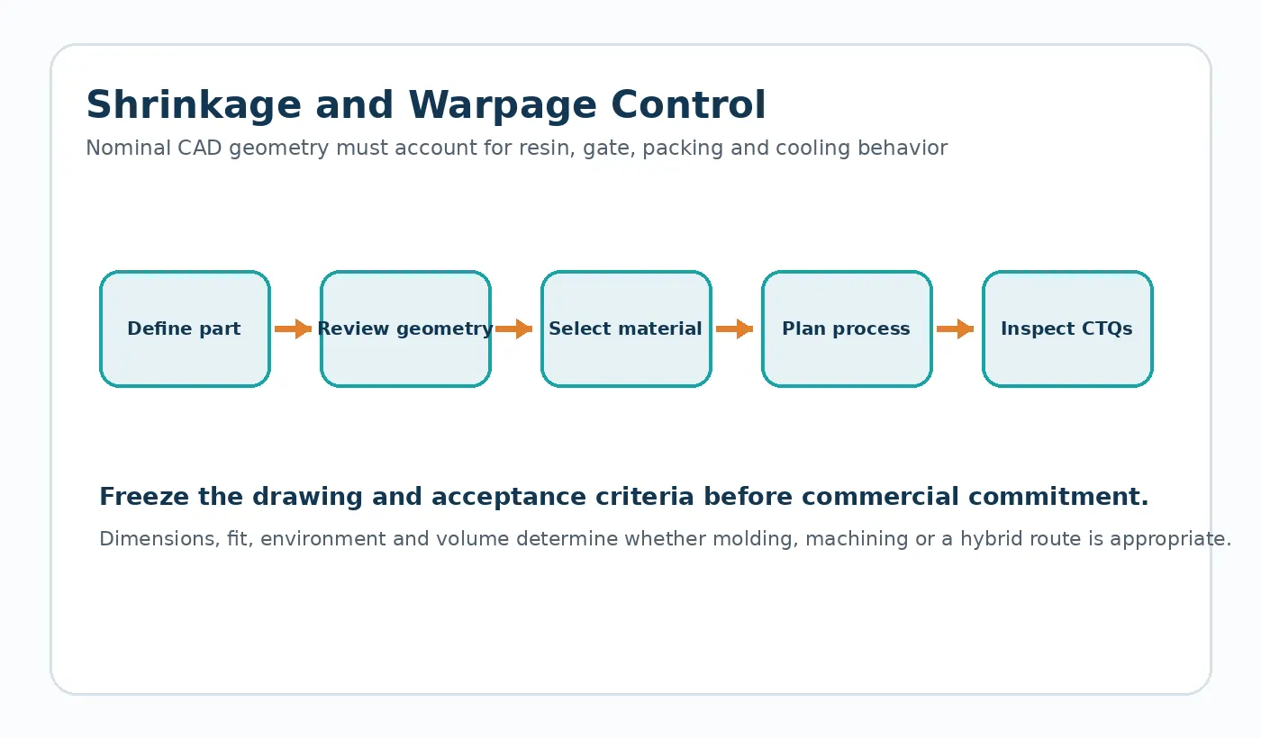
Validate critical flatness, hole position and assembly loads in the molded orientation of the production part.
For Glass-Fibre-Reinforced Plastic Housing Design, close the DFM loop by updating the controlled CAD/drawing and sample plan. A recommendation that never reaches the released revision cannot be inspected consistently in production.

Supplier brief
Before requesting a price for glass-fibre-reinforced plastic housing design, identify the current drawing revision, production quantity, material constraint and the feature that most strongly affects function. Ask the supplier to flag any deviation from those inputs in the quotation so technical alternatives stay visible.
Praktyczny przegląd projektu dla tej decyzji
Obudowa DFM rozpoczyna się od funkcjonalnej mapy ścian. Należy zachować przemyślane przejścia między ścianami, stosować żebra i występy do przenoszenia zdefiniowanych obciążeń, zapewnić pochylenie w miejscu, gdzie narzędzie wymaga zwolnienia, oraz uwzględnić interakcje między punktami wlewu i wyrzutu a powierzchniami kosmetycznymi i wymiarowymi. Dostawca powinien przeanalizować te decyzje pod kątem wybranej żywicy i układu narzędzi.
Zapisz założenia na rysunku lub w zapytaniu ofertowym (RFQ), aby dostawca mógł je potwierdzić przed złożeniem oferty. Jeśli wartość jest nieznana, oznacz ją jako element inżynieryjny, zamiast kopiować ogólny numer katalogowy, który może nie pasować do zestawu.
Arkusz weryfikacyjny
- Nominalna ściana i przejścia
- Ścieżka obciążenia żebra/wypustki
- Projekty i podcięcia
- Obciążenia wkładek/elementów złącznych
- Ograniczenia bramy / rozdzielenia / wyrzutnika
- Płaskość i krytyczne punkty odniesienia
Użyj pierwszej próbki, aby zamknąć te punkty, zarówno pod względem wymiarowym, jak i odpowiedniej kontroli funkcjonalnej. Wszelkie akceptowane odchylenia powinny zostać odnotowane podczas kontroli przed powtórną produkcją.

























