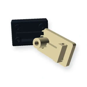
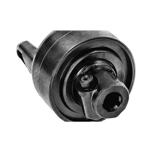
Custom Injection Molded Parts
Drawing-specific molded componentsUse this family when the geometry is defined by your assembly rather than by a standard gear or sprocket form.A custom molded part should be quoted from the assembly interface outward. Start by identifying the surfaces that locate the part, then separate functional dimensions from cosmetic surfaces and packaging geometry. This prevents the tool design from being driven by features that have little effect on service performance.What to define before opening an RFQCAD revision and critical datumsResin or environmental constraintsExpected quantity and tooling life expectationsInserts, undercuts, texture or cosmetic zonesSample and production acceptance methodEarly DFM is especially valuable for wall transitions, bosses, inserts and undercuts because those features determine tool actions, cooling balance and ejection. If the CAD is still changing, state which interfaces are frozen and which remain open to supplier feedback.How to use this categoryThe product cards below are linked to the live WooCommerce catalogue for Custom Injection Molded Parts. Open the closest geometry first, then compare its RFQ guidance against your drawing. If no listed product matches the interface, use the custom component route rather than forcing the part into the wrong family.
Showing all 2 results