Wybierz rodzinę produktów, a następnie zdefiniuj dane wejściowe sterujące
Poniższy katalog jest uporządkowany wokół geometrii i zastosowania komponentów, a nie wokół ogólnych nazw żywic. Każda strona produktu zawiera wyjaśnienia dotyczące wymiarów, materiałów i informacji produkcyjnych potrzebnych do sporządzenia użytecznej oferty.
W przypadku istniejącej części dołącz rysunek lub odniesienie do próbki. W przypadku nowego projektu dodaj informacje o współpracujących częściach i określ, które wymiary lub charakterystyki ruchu są kluczowe.
Typowe trasy selekcji
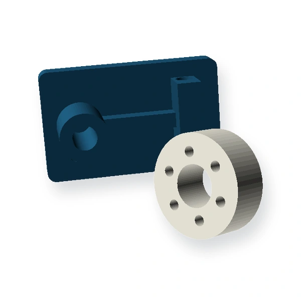
Części formowane na zamówienie
Rysunki obudów, prowadnic, pokryw, cech konstrukcyjnych i mechanizmów funkcjonalnych.
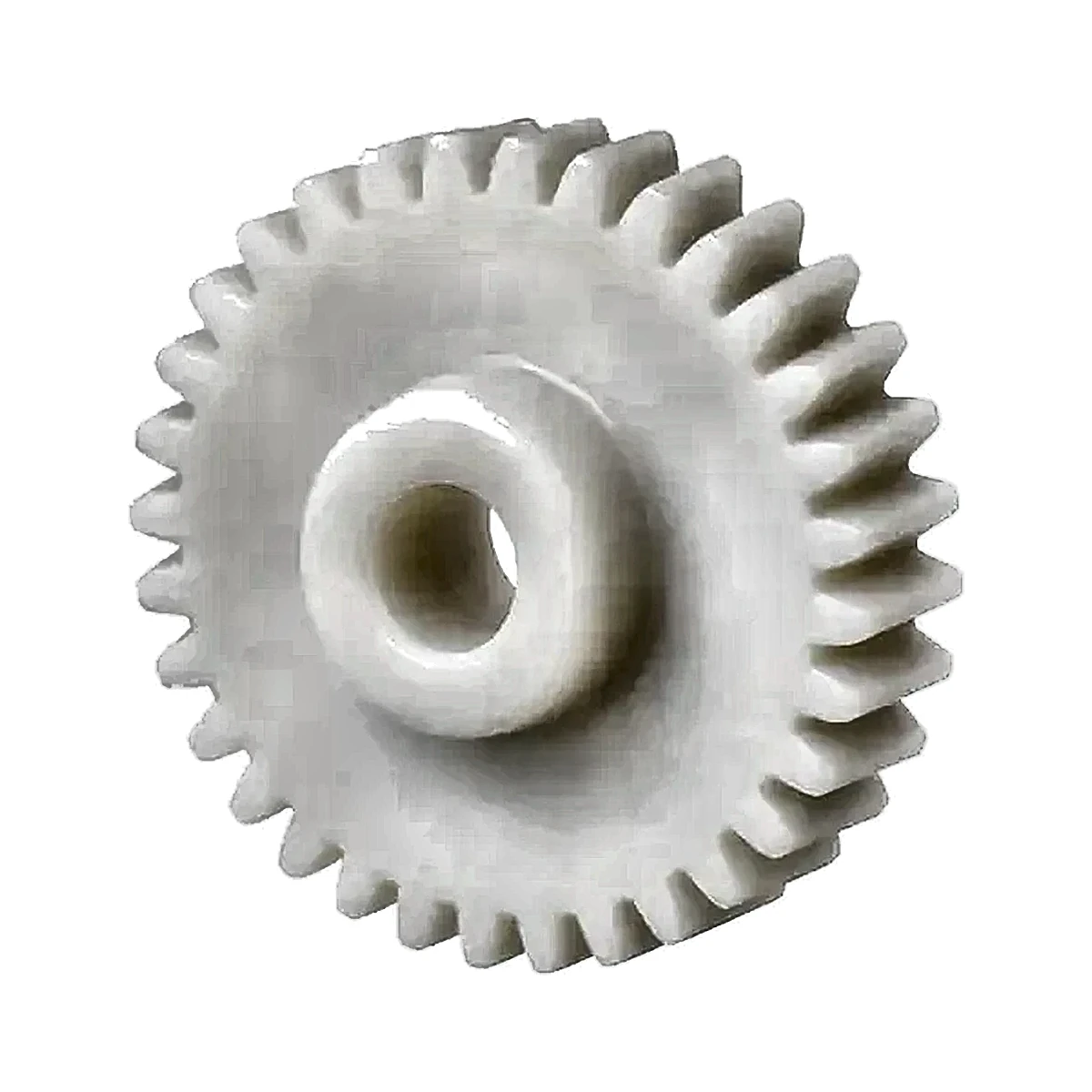
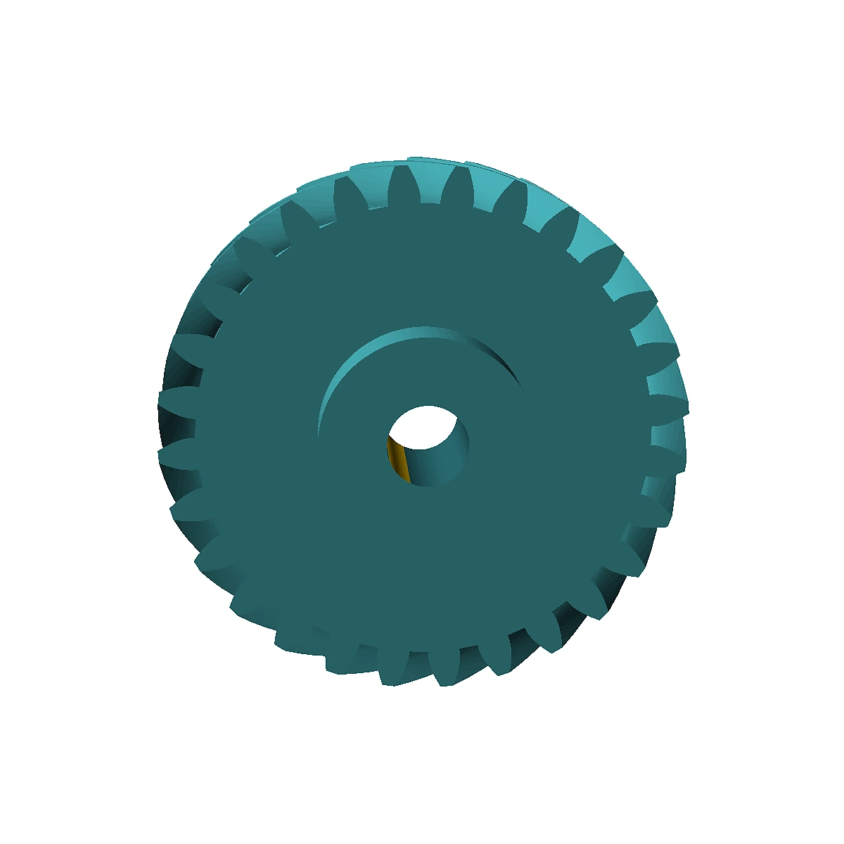
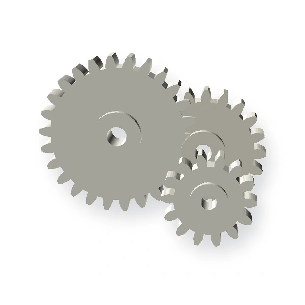
Plastikowe koła zębate i zębatki
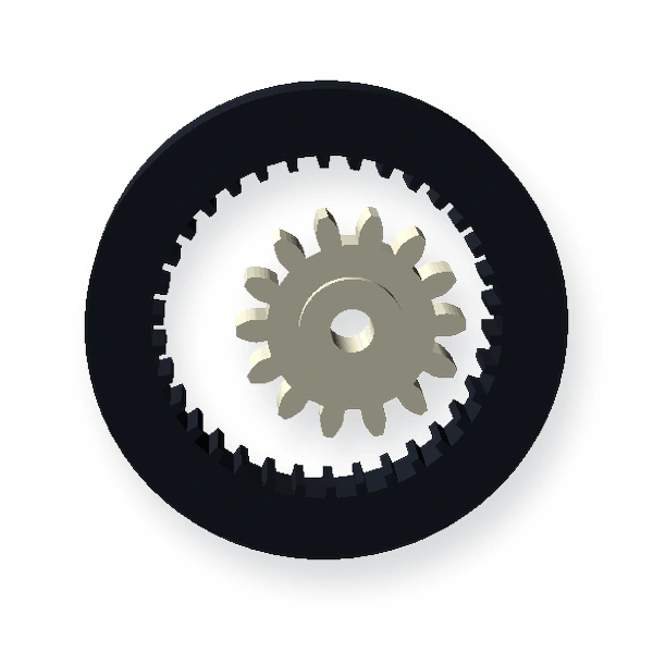
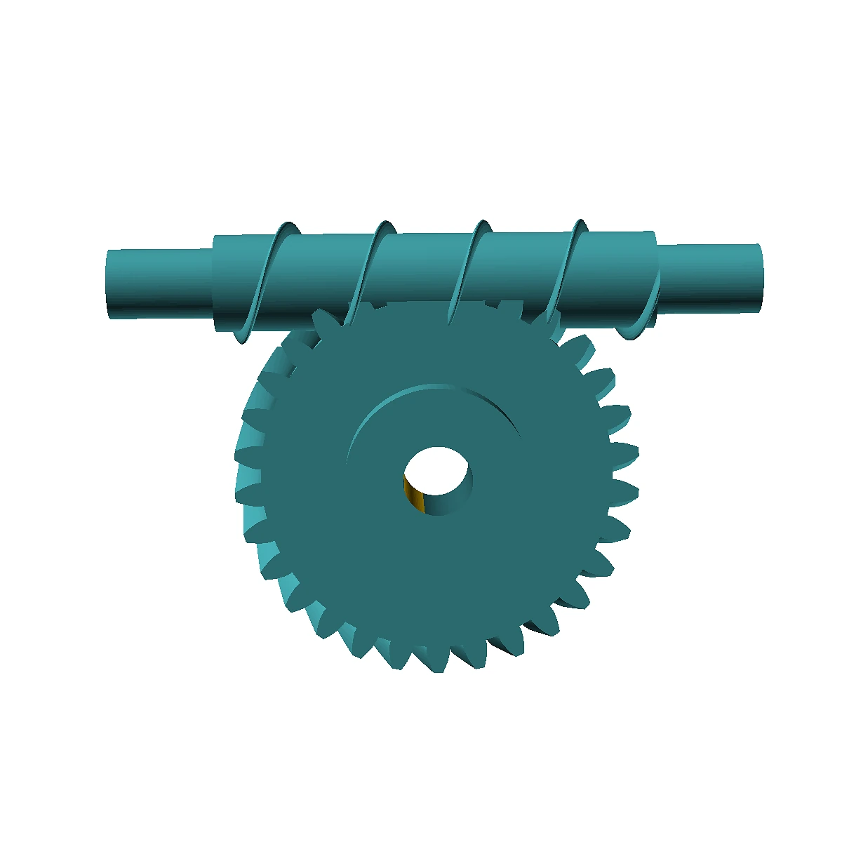
Geometrie ruchu ostrogowego, śrubowego, stożkowego, ślimakowego, wewnętrznego, planetarnego i liniowego.
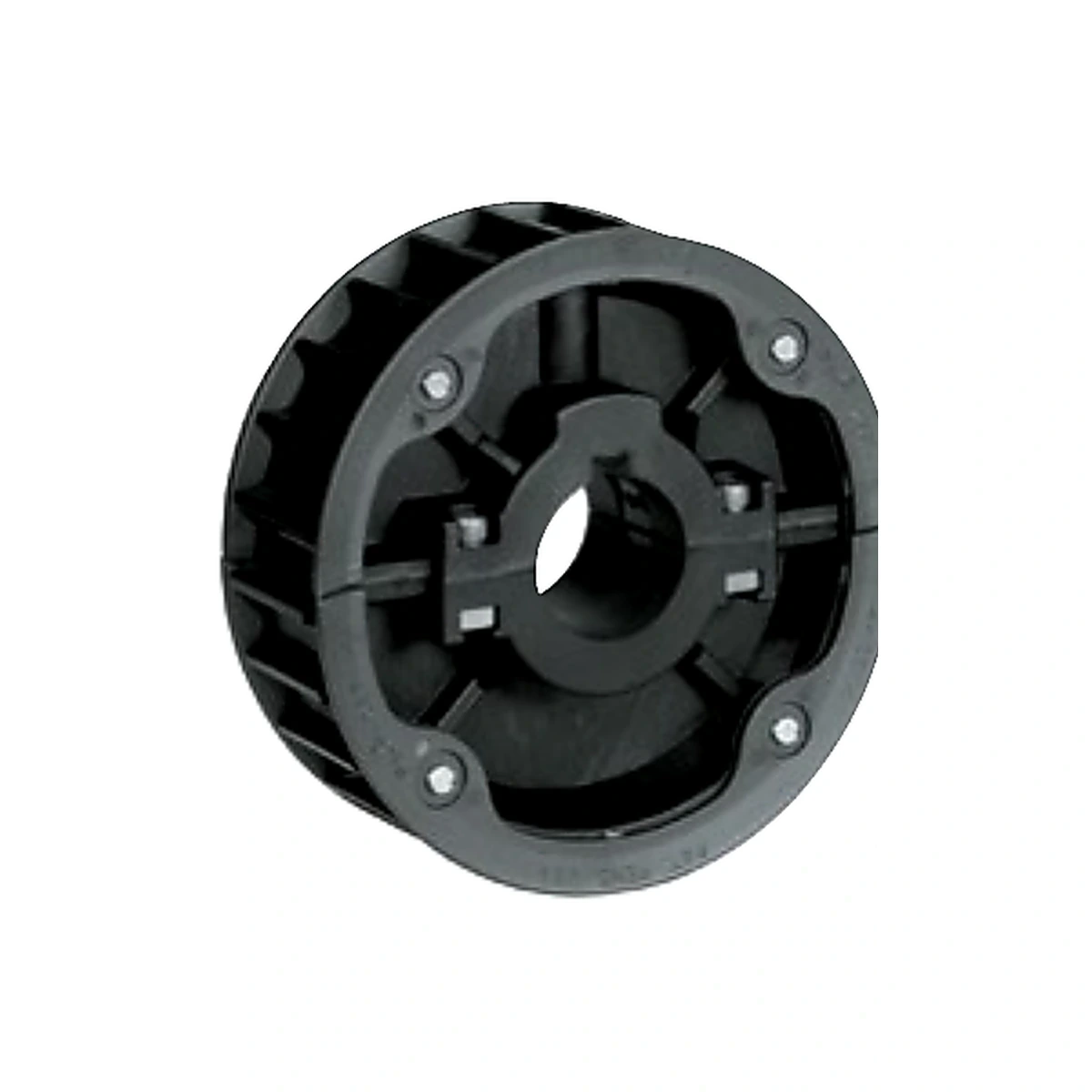
Plastikowe zębatki
Komponenty napędu łańcuchowego dobierane są na podstawie serii łańcucha, liczby zębów, otworu, piasty i środowiska pracy.
Jak zbudowany jest katalog
Użyj geometrii jako pierwszego filtra. Zębatka, koło zębate stożkowe, koło zębate wewnętrzne, koło ślimakowe i koło łańcuchowe mogą być wykonane z tworzyw konstrukcyjnych, ale wymagają różnych informacji dotyczących dopasowania i innych danych montażowych. Dlatego strony rodziny produktów zaczynają się od interfejsu mechanicznego, zamiast prezentować długą listę żywic.
| Punkt początkowy | Otwórz tę trasę, gdy… | Zanieś do przeglądu |
|---|---|---|
| Rodzina geometrii standardowej | Element ten można rozpoznać po kole zębatym, listwie zębatej lub kole zębatym. | Układ zębaty lub łańcuchowy, element współpracujący, interfejs wału i obciążenie. |
| Komponent formowany na zamówienie | Kształt jest definiowany przez zespół i nie można go wybrać ze standardowej rodziny. | CAD, dane odniesienia, mapa ścienna, wkładki, obciążenia, środowisko i objętość. |
| Wymiana oparta na materiale | Starsza część metalowa lub plastikowa ma znany problem w terenie. | Istniejąca próbka, rodzaj uszkodzenia, powierzchnie styku i wymagania, jakie musi spełniać nowy materiał. |
Nie wybieraj zbyt wcześnie drogi produkcyjnej
Formowanie wtryskowe jest zazwyczaj oceniane pod kątem rocznego zapotrzebowania, geometrii, dostępu do narzędzi, konstrukcji ścianek i wymagań powtarzalności. Obróbka skrawaniem może być bardziej praktyczna w przypadku mniejszych ilości, większych półfabrykatów, odlewanych elementów nylonowych lub projektów, w których geometria wciąż ulega zmianom. Niektóre projekty łączą formowanie z kontrolowanym otworem wtórnym, punktem odniesienia lub operacją wstawiania.
Prawidłowa trasa to taka, która spełnia wymagania rysunku funkcjonalnego, przy akceptowalnym ryzyku procesowym i całkowitym koszcie projektu. Prześlij zarówno ilość, jak i status wersji, aby uniknąć proponowania oprzyrządowania dla projektu, który jest nadal w trakcie realizacji.
How to compare product pages without guessing
Start with the interface that cannot move: shaft spacing, chain standard, rack pitch line, housing datums or assembly envelope. Then define the motion geometry and only after that compare materials and manufacturing routes. A familiar product name is not a complete specification. Two parts that look alike can require different tooth forms, bore fits, resin conditions or inspection methods.
Gear pages
Confirm module or DP, pressure angle, tooth count, face width, helix or bevel data where applicable, mating member, center distance or shaft angle, bore/hub details and the required backlash condition.
Rack and sprocket pages
For racks, define pitch geometry, mounting datum, length/joints and pinion mesh. For sprockets, begin with chain standard and pitch, then define tooth count, strand, bore, hub and shaft retention.
Części formowane na zamówienie
Identify wall sections, ribs, bosses, inserts, undercuts, cosmetic zones, sealing or bearing interfaces, gate/ejector restrictions and the dimensions that determine assembly function.
RFQ data that shortens the first engineering loop
A useful RFQ links the drawing revision to annual or batch quantity, material requirement or service conditions, mating components, critical dimensions, inspection expectations and any approved sample. Where a specification is still open, state the functional target rather than inserting a tight tolerance by default. That gives engineering room to choose a process and control plan that match the real risk.
For replacement components, send photographs only as context. Tooth geometry, shaft interfaces and datums still need dimensions or a sample that can be measured. For new molded parts, identify which surfaces may carry a gate, parting line or ejector witness and which surfaces are functionally or cosmetically restricted.
What makes a product record useful for sourcing
A product title is only a route into the engineering conversation. The quotation still needs the geometry that controls motion or fit, the mating interface, service environment, quantity and an acceptance method. For gears that means the tooth system and the bore-to-tooth relationship; for racks it means pitch line, length, joints and mounting datum; for sprockets it means the chain standard, tooth count, bore, hub and strand; for custom molded parts it means the CAD model, wall strategy, inserts and assembly datums.
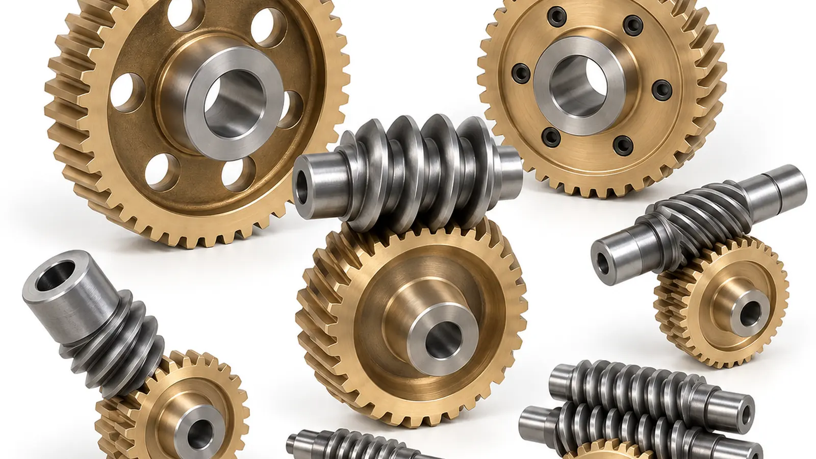
Photographs are deliberately treated as visual references rather than dimensional evidence. A photograph can confirm the component family and show typical construction, but it cannot establish module, backlash, shaft fit or a critical molded dimension. The controlled drawing remains the production definition.
First: freeze the interface
Identify the surfaces, tooth geometry, shaft or mounting features that cannot move without changing the machine.
Second: define the duty
Add load, speed, reversing duty, temperature, moisture, chemicals, lubrication and the expected service cycle.
Third: agree acceptance
Mark CTQs, datums and functional checks so the sample review measures the features that actually control assembly performance.