
Begin bij het mechanisme.
A useful gear tolerance plan focuses on the characteristics that control the mesh and mounting relationship.
Bore-to-tooth runout, tooth-to-tooth variation, overall geometry and the center distance in the assembly all influence working performance. Molding adds material shrinkage and process variation that should be reflected in datum and inspection choices.
Consider an assembly where the bore locates on a steel shaft and the mate is fixed in a molded housing. A tight outside-diameter tolerance on the gear does little if bore runout or housing center distance dominates the mesh. The drawing should therefore distinguish tooth geometry from mounting geometry and place the inspection datum on the feature that actually locates the gear in service.
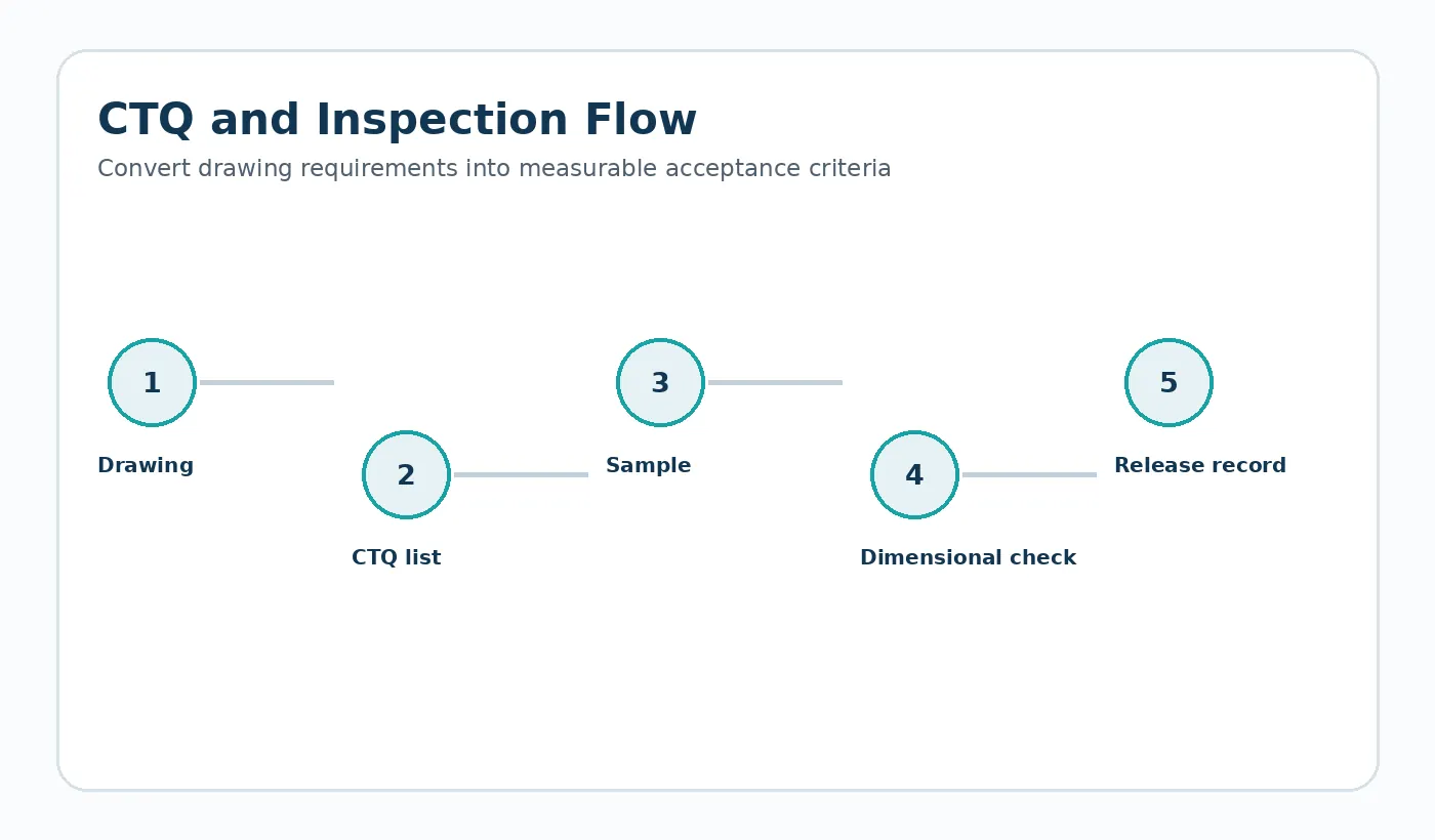
Invoergegevens moeten worden bevroren vóór de offerte.
Define the gear standard/convention, module or DP, pressure angle, bore datum, mating gear, center distance, backlash target and measurement condition.
Plaats deze gegevens waar mogelijk op de gecontroleerde tekening, specificatie of bijlage bij de offerteaanvraag. Door ze buiten informele berichtenwisselingen te houden, worden vergelijkingen met leveranciers en latere herzieningen gemakkelijker te beheren.
Wat kan de aanname ongeldig maken?
Overtightening every drawing dimension can increase tooling and inspection cost without controlling the actual mesh.
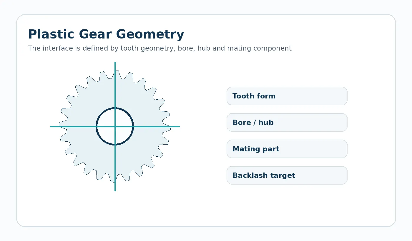
Verificatiestrategie
Combine dimensional gear checks with an assembled roll or functional test when that better represents the mechanism.
For Injection Molded Gear Tolerances, close the DFM loop by updating the controlled CAD/drawing and sample plan. A recommendation that never reaches the released revision cannot be inspected consistently in production.
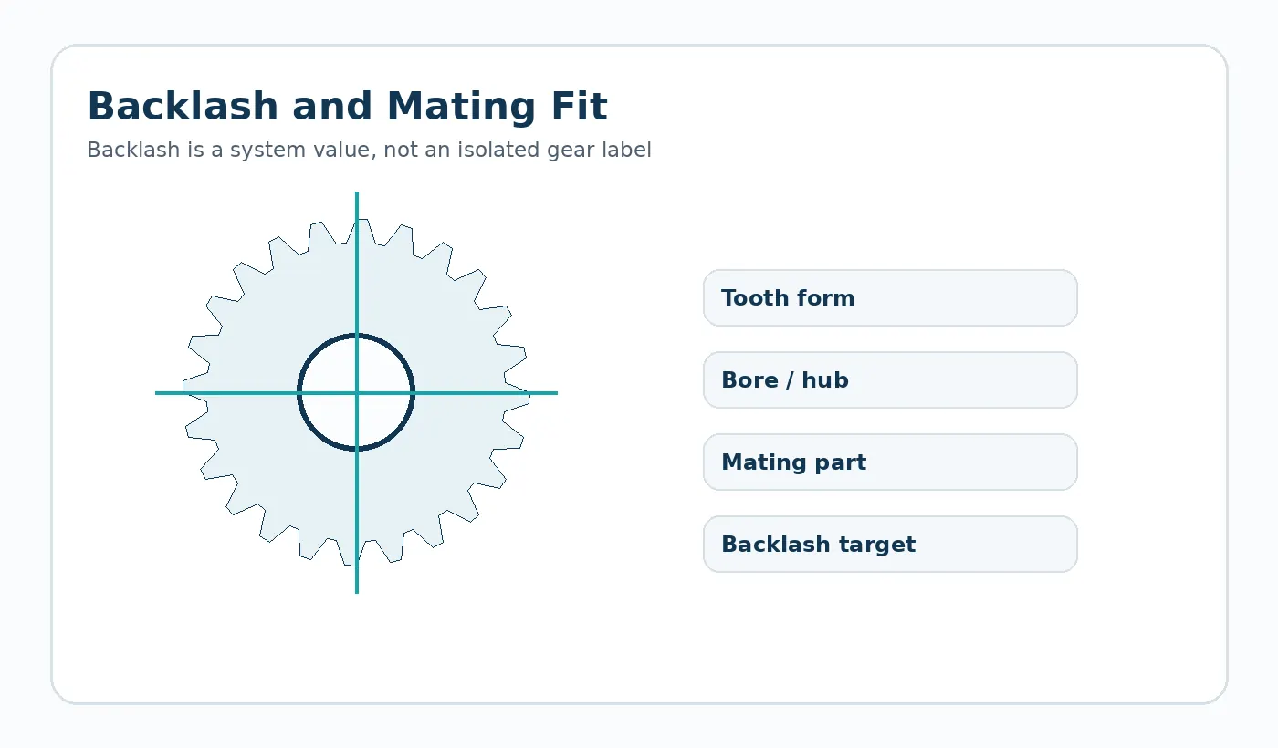
Inkoopchecklist
Before requesting a price for injection molded gear tolerances, identify the current drawing revision, production quantity, material constraint and the feature that most strongly affects function. Ask the supplier to flag any deviation from those inputs in the quotation so technical alternatives stay visible.
Practical design review for this decision
Tolerance should be allocated from the assembly backward. Start with required working backlash or position, then include center-distance variation, tooth-to-bore runout, shaft/bearing clearance, material movement and measurement uncertainty. Tightening every free-part dimension can increase cost without protecting the assembled condition.
Record the assumptions on the drawing or RFQ so the supplier can confirm them before quoting. When a value is unknown, identify it as an open engineering item rather than copying a generic catalogue number that may not match the assembly.
Verification worksheet
- Working rather than nominal clearance
- Bore-to-tooth or rack-to-mount datum relationship
- Mating-part tolerance
- Inspection temperature / conditioning
- Functional roll, mesh or position check
- Acceptance method agreed before sampling
Use the first sample to close these points with both dimensional evidence and the relevant functional check. Any accepted deviation should be captured in the controlled revision before repeat production.

























