
Treat the transmission as a coupled system
Plastic gears and racks can be effective in compact motion systems when the tooth geometry, center distance, shafts, bearings, housing stiffness and material pair are considered together. A gear that is acceptable by itself can still produce noise, wear or poor positioning if the supporting geometry is not controlled.
For motion-control applications, define ratio, speed, torque, duty cycle, backlash sensitivity and the permissible change over the operating temperature range.
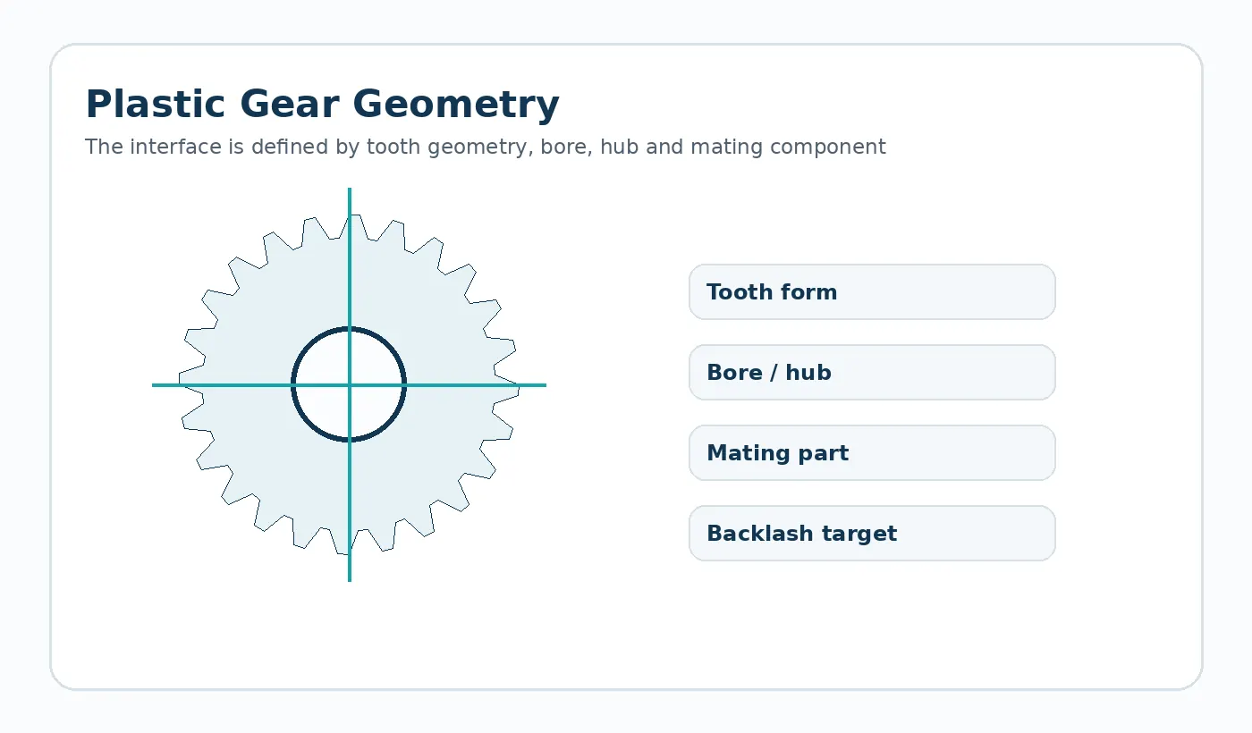
System-level checks
Mesh geometry
Module or DP, pressure angle, helix or bevel geometry, center distance and mating tooth counts.
Support geometry
Bore fit, shaft runout, bearing location and housing alignment affect the working mesh.
Functional target
State whether noise, wear life, positioning, weight or corrosion is the dominant design objective.
Backlash belongs to the full tolerance chain
Working backlash is created by tooth geometry and center distance together. Shaft runout, bearing clearance, housing deflection and polymer dimensional change all influence the result. Tightening the gear tolerance alone cannot correct an uncontrolled support structure.
For precision motion, build the tolerance path from input shaft to output mechanism and identify which contributors dominate. That is a stronger basis for specifying gear accuracy than applying the same tolerance to every component.
Load and thermal behavior
Plastic teeth deflect more than metal teeth under the same geometry and load. This can be useful for damping impact but must be accounted for where positional stiffness is important. Local temperature can also rise from motor heat or sliding contact.
Validate at representative torque and duty, and check whether backlash or noise changes after the drivetrain reaches a stable operating temperature.
Motion-control RFQ inputs
- Ratio and full gear-pair or gear-train geometry
- Input/output speed and torque
- Reversals, acceleration and duty cycle
- Allowable backlash or positioning error
- Shaft, bearing and housing datums
- Operating temperature and material constraints
이 애플리케이션에 대한 검증 계획
기계 인터페이스를 중심으로 초기 샘플 검사를 수행하십시오. 장착 기준점, 결합 부품 또는 체인, 예상 하중 방향, 대표적인 속도/사이클 패턴 및 사용 환경을 확인하십시오. 위치 또는 백래시가 중요한 경우, 단순히 자유로운 부품만 승인하는 것이 아니라 대표적인 조건 및 사이클링 후 조립된 메커니즘을 측정하십시오.
부품 도면에서 간과하기 쉬운 현장 제약 조건(예: 가드 간극, 세척제, 인근 모터 열, 지지되지 않은 랙 간격, 역회전 작동, 기어 중심을 고정하는 베어링 배열 등)을 문서화하십시오. 이러한 세부 사항은 치수적으로는 문제가 없는 부품이 실제 사용 환경에서 다르게 작동하는 이유를 설명하는 데 도움이 될 수 있습니다.
신청 승인 레일
출고 전에 부품을 다음 네 가지 기준에 맞춰 검증해야 합니다. 작동 조건, 결합 인터페이스, 치수 허용 오차에 사용되는 환경 조건, 그리고 실제 조립 상태를 재현하는 기능 테스트입니다. 이러한 검증을 통해 명목상 올바른 부품이라도 실제 사용 환경과 일치하지 않는 조건에서 승인되는 것을 방지할 수 있습니다.
의무
최대 부하 및 정상 부하, 속도, 역회전, 사이클 프로파일 및 예상 서비스 간격.
인터페이스
결합 형상, 지지대, 정렬, 체결 부품 또는 축 맞춤 및 측정에 사용되는 기준 체계.
수락
반복 생산 전에 조건 상태, 중요 치수, 시각적 기준 및 조립 또는 동작 검사에 대한 합의가 이루어져야 합니다.
Information to include in the application review
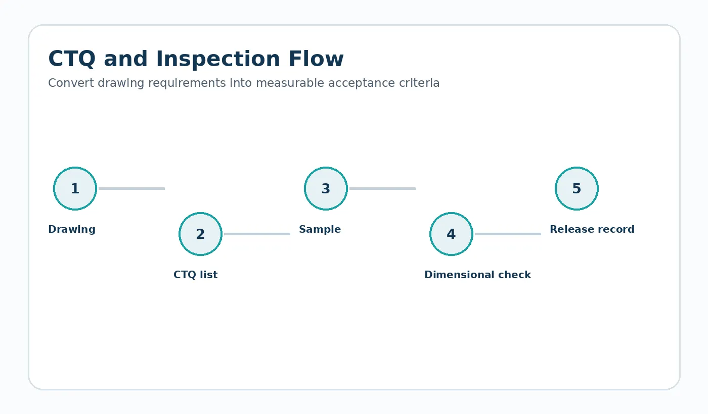
Document the complete operating envelope rather than only nominal speed or load. Include starts and reversals, worst-case temperature and moisture, cleaning chemicals or lubricants, shaft and bearing support, the mating material, available installation space and any field-replacement constraint. If noise, backlash, wear or positional repeatability is the reason for the project, state that explicitly so the drawing and inspection plan can focus on the real problem.
For first samples, define what will be checked in the component and what will be checked in the machine. A dimensional report verifies the drawing; an assembly or functional test verifies that the selected datums, fits and material condition produce the required behavior. Both are useful when the mechanism is sensitive to cumulative tolerances.

























