
Treat the transmission as a coupled system
Plastic gears and racks can be effective in compact motion systems when the tooth geometry, center distance, shafts, bearings, housing stiffness and material pair are considered together. A gear that is acceptable by itself can still produce noise, wear or poor positioning if the supporting geometry is not controlled.
For motion-control applications, define ratio, speed, torque, duty cycle, backlash sensitivity and the permissible change over the operating temperature range.
System-level checks
Mesh geometry
Module or DP, pressure angle, helix or bevel geometry, center distance and mating tooth counts.
Support geometry
Bore fit, shaft runout, bearing location and housing alignment affect the working mesh.
Functional target
State whether noise, wear life, positioning, weight or corrosion is the dominant design objective.
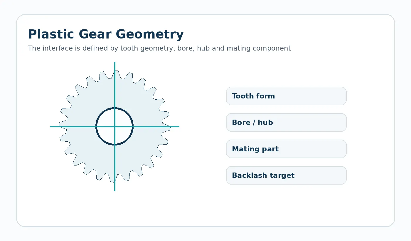
Backlash belongs to the full tolerance chain
Working backlash is created by tooth geometry and center distance together. Shaft runout, bearing clearance, housing deflection and polymer dimensional change all influence the result. Tightening the gear tolerance alone cannot correct an uncontrolled support structure.
For precision motion, build the tolerance path from input shaft to output mechanism and identify which contributors dominate. That is a stronger basis for specifying gear accuracy than applying the same tolerance to every component.
Load and thermal behavior
Plastic teeth deflect more than metal teeth under the same geometry and load. This can be useful for damping impact but must be accounted for where positional stiffness is important. Local temperature can also rise from motor heat or sliding contact.
Validate at representative torque and duty, and check whether backlash or noise changes after the drivetrain reaches a stable operating temperature.
Motion-control RFQ inputs
- Ratio and full gear-pair or gear-train geometry
- Input/output speed and torque
- Reversals, acceleration and duty cycle
- Allowable backlash or positioning error
- Shaft, bearing and housing datums
- Operating temperature and material constraints
Valideringsplan for denne applikasjonen
Bygg den første prøvekontrollen rundt maskingrensesnittet. Bekreft monteringsdata, motstående del eller kjede, forventet lastretning, representativt hastighets-/syklusmønster og driftsmiljø. Der posisjon eller klaring er viktig, mål den monterte mekanismen etter representativ kondisjonering og sykling i stedet for å bare godkjenne den frie komponenten.
Dokumenter eventuelle feltbegrensninger som er lette å overse på en komponenttegning: beskyttelsesklaring, spylingskjemikalier, varme fra motoren i nærheten, ustøttet tannstangspenn, reverseringsdrift eller lagerarrangementet som fester girsentrene. Disse detaljene forklarer ofte hvorfor en dimensjonalt akseptabel del oppfører seg annerledes under drift.
Søknadsgodkjenningsskinne
Før frigivelse, knytt komponenten tilbake til fire kontroller: driftsoppgaven, tilkoblingsgrensesnittet, miljøforholdene som brukes for dimensjonsgodkjenning og funksjonstesten som representerer den faktiske monteringen. Disse kontrollene forhindrer at en nominelt korrekt del blir godkjent under forhold som ikke samsvarer med tjenesten.
Plikt
Topp- og normalbelastning, hastighet, reverseringer, syklusprofil og forventet serviceintervall.
Grensesnitt
Monteringsgeometri, støtte, justering, feste- eller akseltilpasning og nullpunktskjemaet som brukes for måling.
Godkjennelse
Kondisjoneringstilstand, kritiske dimensjoner, visuelle kriterier og en monterings- eller bevegelseskontroll avtalt før gjentatt produksjon.
Information to include in the application review
Document the complete operating envelope rather than only nominal speed or load. Include starts and reversals, worst-case temperature and moisture, cleaning chemicals or lubricants, shaft and bearing support, the mating material, available installation space and any field-replacement constraint. If noise, backlash, wear or positional repeatability is the reason for the project, state that explicitly so the drawing and inspection plan can focus on the real problem.
For first samples, define what will be checked in the component and what will be checked in the machine. A dimensional report verifies the drawing; an assembly or functional test verifies that the selected datums, fits and material condition produce the required behavior. Both are useful when the mechanism is sensitive to cumulative tolerances.

























