
İletimi birleşik bir sistem olarak ele alın.
Plastik dişliler ve kremayerler, diş geometrisi, merkez mesafesi, miller, yataklar, gövde rijitliği ve malzeme çifti birlikte değerlendirildiğinde kompakt hareket sistemlerinde etkili olabilirler. Tek başına kabul edilebilir bir dişli, destekleyici geometri kontrol edilmediği takdirde yine de gürültüye, aşınmaya veya kötü konumlandırmaya neden olabilir.
Hareket kontrol uygulamaları için oran, hız, tork, görev döngüsü, boşluk hassasiyeti ve çalışma sıcaklığı aralığındaki izin verilen değişimi tanımlayın.
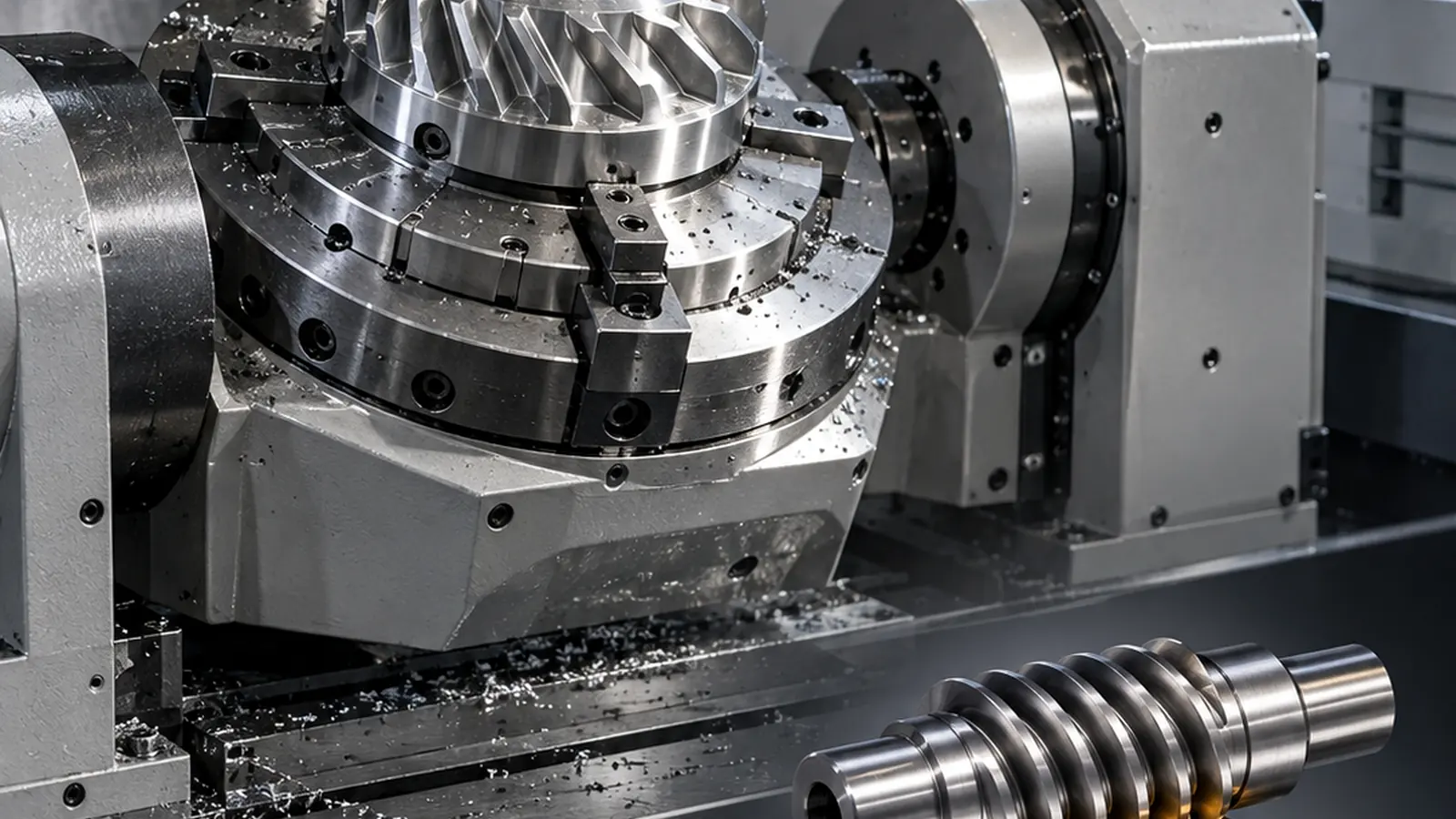
Sistem düzeyinde kontroller
Ağ geometrisi
Modül veya DP, basınç açısı, helis veya eğim geometrisi, merkez mesafesi ve eşleşen diş sayısı.
Destek geometrisi
Delik uyumu, mil salınımı, yatak konumu ve gövde hizalaması, çalışma dişlisini etkiler.
İşlevsel hedef
Tasarımda gürültü, kullanım ömrü, konumlandırma, ağırlık veya korozyonun hangisinin baskın hedef olduğunu belirtin.
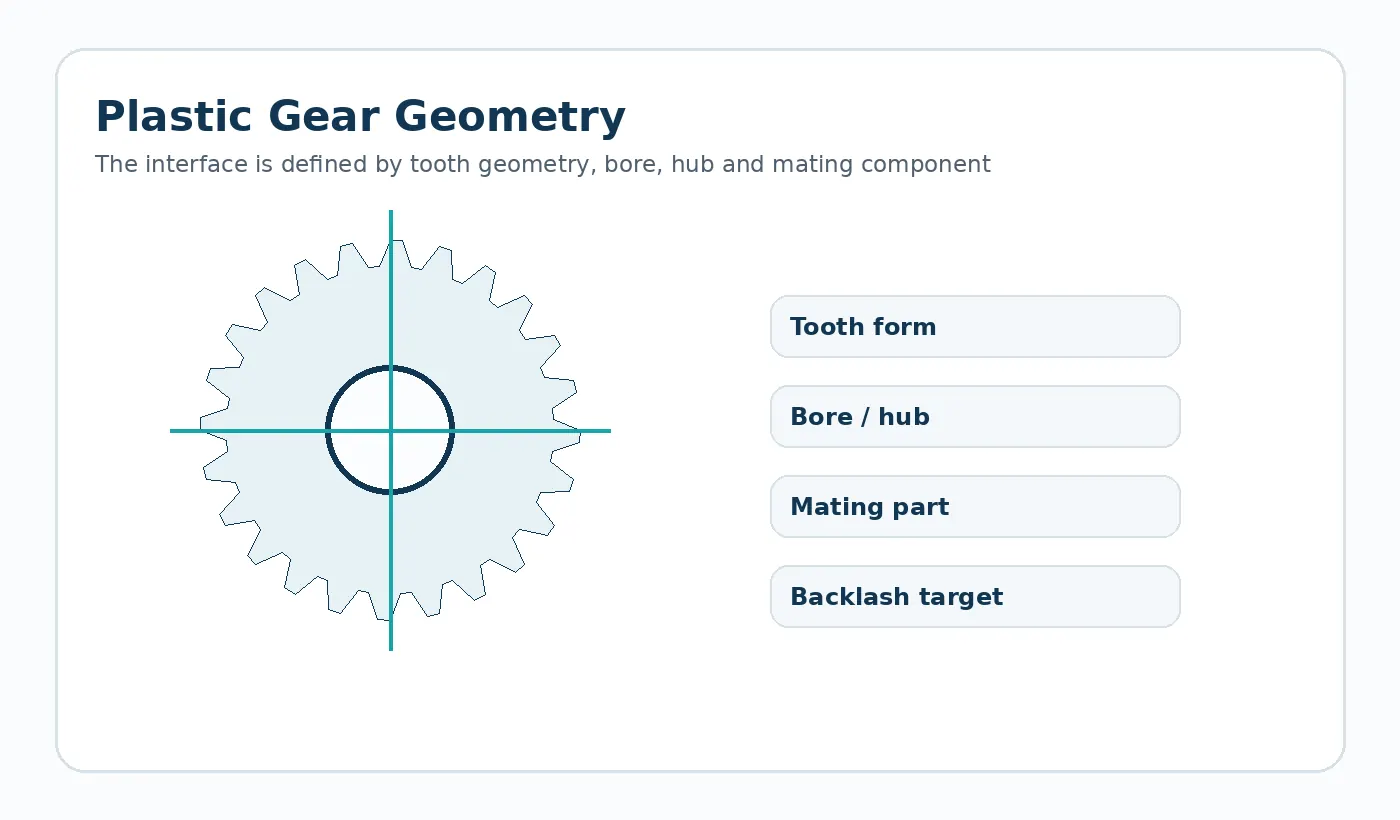
Geri tepme, tam tolerans zincirine aittir.
Çalışma boşluğu, diş geometrisi ve merkez mesafesinin birlikte etkisiyle oluşur. Mil salınımı, yatak boşluğu, gövde deformasyonu ve polimer boyutundaki değişiklikler sonucu etkiler. Sadece dişli toleransını sıkılaştırmak, kontrolsüz bir destek yapısını düzeltemez.
Hassas hareket için, giriş milinden çıkış mekanizmasına kadar tolerans yolunu oluşturun ve hangi etkenlerin baskın olduğunu belirleyin. Bu, her bileşene aynı toleransı uygulamaktan daha güçlü bir dişli hassasiyeti belirleme temelidir.
Yük ve termal davranış
Plastik dişler, aynı geometri ve yük altında metal dişlere göre daha fazla esner. Bu, darbeyi sönümlemek için faydalı olabilir, ancak konumsal sertliğin önemli olduğu durumlarda dikkate alınmalıdır. Ayrıca, motor ısısından veya kayma temasından dolayı yerel sıcaklık da artabilir.
Temsili tork ve çalışma koşullarında doğrulama yapın ve aktarma organlarının kararlı bir çalışma sıcaklığına ulaştıktan sonra boşluk veya gürültüde değişiklik olup olmadığını kontrol edin.
Hareket kontrolü RFQ girişleri
- Oran ve tam dişli çifti veya dişli takımı geometrisi
- Giriş/çıkış hızı ve torku
- Tersine çevirmeler, hızlanma ve görev döngüsü
- İzin verilen geri tepme veya konumlandırma hatası
- Mil, yatak ve gövde referans noktaları
- Çalışma sıcaklığı ve malzeme kısıtlamaları
Validation plan for this application
Build the first-sample check around the machine interface. Confirm the mounting datums, mating part or chain, expected load direction, representative speed/cycle pattern and the service environment. Where position or backlash matters, measure the assembled mechanism after representative conditioning and cycling rather than approving only the free component.
Document any field constraint that is easy to miss on a component drawing: guard clearance, washdown chemical, nearby motor heat, unsupported rack span, reversing duty, or the bearing arrangement that fixes gear centers. These details often explain why a dimensionally acceptable part behaves differently in service.
Application acceptance rail
Before release, tie the component back to four controls: the operating duty, the mating interface, the environmental condition used for dimensional acceptance and the functional test that represents the real assembly. These controls prevent a nominally correct part from being approved under conditions that do not match service.
Duty
Peak and normal load, speed, reversals, cycle profile and expected service interval.
Interface
Mating geometry, support, alignment, fastener or shaft fit and the datum scheme used for measurement.
Acceptance
Conditioning state, critical dimensions, visual criteria and an assembly or motion check agreed before repeat production.
Information to include in the application review
Document the complete operating envelope rather than only nominal speed or load. Include starts and reversals, worst-case temperature and moisture, cleaning chemicals or lubricants, shaft and bearing support, the mating material, available installation space and any field-replacement constraint. If noise, backlash, wear or positional repeatability is the reason for the project, state that explicitly so the drawing and inspection plan can focus on the real problem.
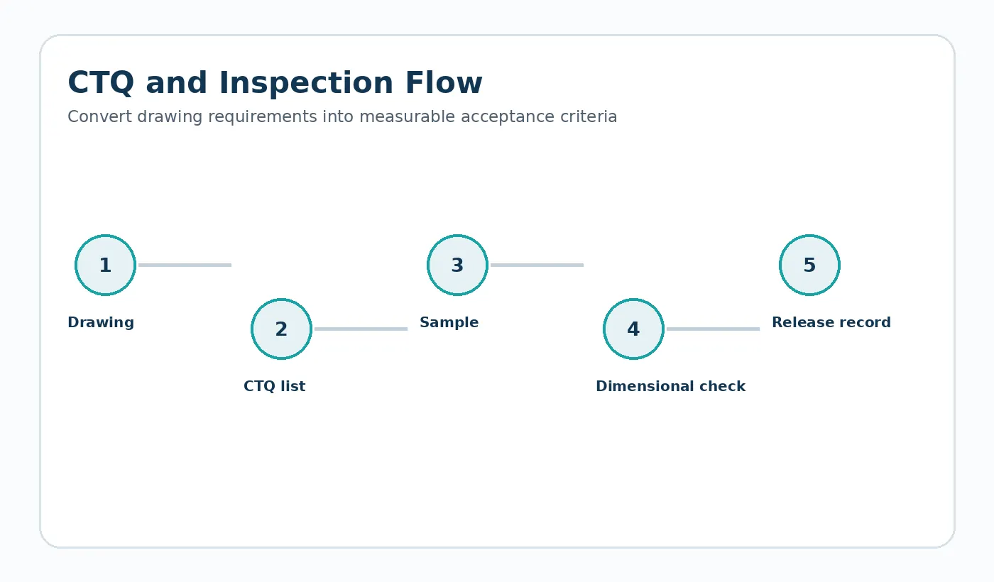
For first samples, define what will be checked in the component and what will be checked in the machine. A dimensional report verifies the drawing; an assembly or functional test verifies that the selected datums, fits and material condition produce the required behavior. Both are useful when the mechanism is sensitive to cumulative tolerances.

























