
Custom engineering begins with the interface
For a non-standard part, the fastest route to a meaningful review is to show how the component fits into the assembly. A standalone image rarely captures the information needed to judge draft, wall thickness, shaft fits, gear mesh, inserts or inspection access.
Share the drawing, mating geometry and application conditions together. If a legacy part is being replaced, photographs and a physical sample can be useful supplements to the controlled dimensions.
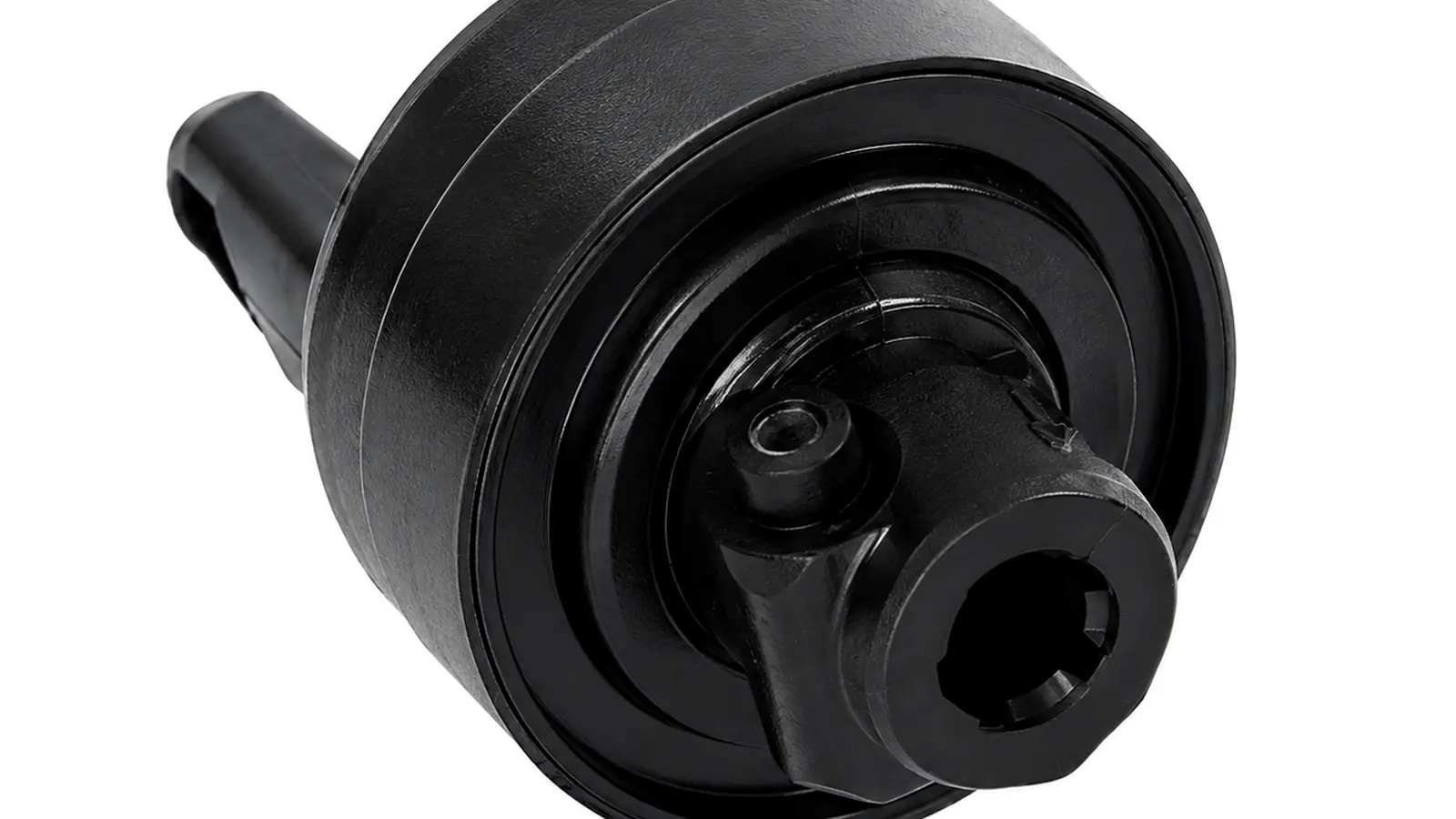
Engineering review priorities
Functional datums
Identify the surfaces, bores, teeth or mounting features that locate the part in service.
Material constraints
State fixed resin requirements, prohibited materials, colour, reinforcement, regulatory or environmental constraints where relevant.
Change risk
Flag dimensions likely to change after prototype evaluation so tooling decisions can be staged appropriately.
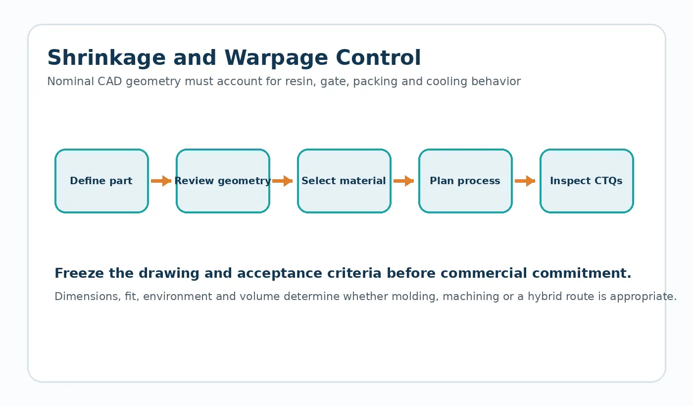
Reverse engineering and replacement work
When the only starting point is an existing part, measured geometry should be separated into functional interfaces, likely manufacturing variation and wear. Copying every measured feature from a used sample can reproduce damage or distortion. A better replacement drawing identifies the shaft fits, mounting datums, gear mesh or sliding surfaces that must remain interchangeable.
If the previous part failed, describe the failure location and duty at the time. Cracking around an insert, wear on a tooth flank and dimensional drift in a hot housing point to different design questions.
Design changes should have a reason
DFM feedback is most useful when each proposed geometry change is tied to tooling, material flow, ejection, inspection or service performance. A radius added for molding should not interfere with a mating metal part; a thicker boss should not create an unnecessary mass opposite a cosmetic surface.
Keep a short decision record beside the drawing revision. This makes later supplier changes or reorders easier because the reasoning behind important interfaces does not disappear with the original email thread.
From prototype to production
| Project stage | Main purpose | Evidence to keep |
|---|---|---|
| Concept/prototype | Confirm envelope, motion and assembly | CAD revision, trial observations, open issues |
| DFM/tooling | Freeze manufacturable geometry | Approved DFM notes, material, tool assumptions |
| First samples | Verify production-process output | Dimensional report, material record, functional results |
| Repeat production | Control the released requirement | Drawing revision, inspection plan, approved change history |
Control the project through revision, datum and decision records
Custom-part projects become unstable when CAD, drawings and sample comments describe different revisions. Use one controlled revision as the quotation basis and record any accepted change to material, gate location, secondary operation or critical dimension before production release.
A supplier can only protect function when the load path and datum logic are visible. Mark the dimensions that affect assembly or motion, identify inserts and fastening loads, and distinguish functional surfaces from cosmetic preferences.
A drawing-led project should have clear decision gates
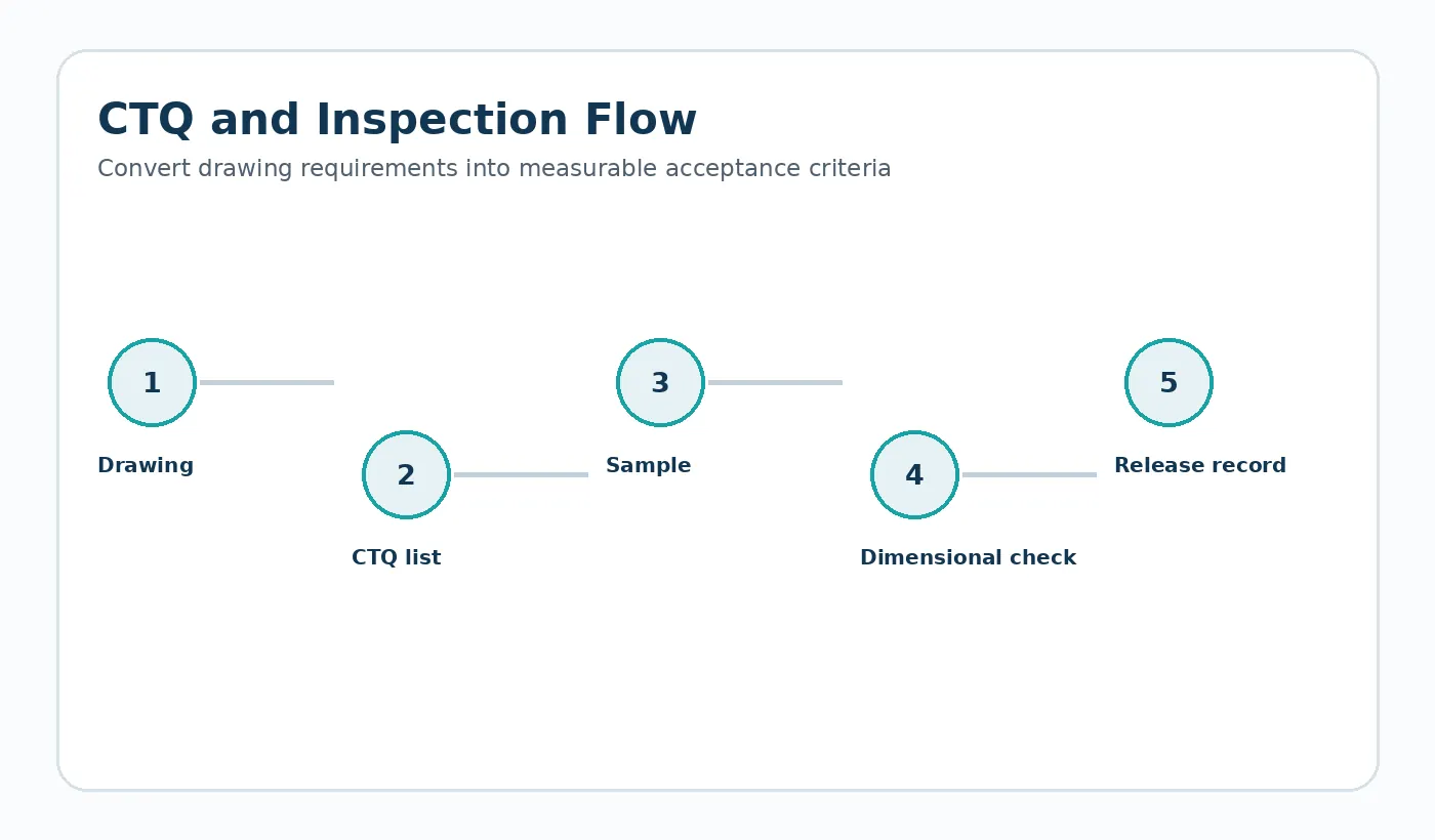
Custom work is easier to control when quotation, DFM, tool release and sample approval are treated as separate decisions. At quotation, the goal is to understand the component function and choose a plausible process. During DFM, the goal is to resolve manufacturing geometry without losing the design intent. Tool release freezes the controlled revision. Sample approval then verifies the agreed CTQs and the part in its mating assembly.
Quotation gate
Drawing revision, quantity, material status, application, mating parts and unresolved design questions are visible.
Tool-release gate
Draft, walls, undercuts, gates, inserts, parting strategy, critical datums and acceptable manufacturing witnesses are agreed.
Sample-approval gate
The inspection state, CTQs and functional test are known before parts arrive, reducing subjective approval loops.
For replacement components, provide the existing sample together with the machine context and failure history. Reverse measurement can reproduce geometry, but it should not blindly reproduce wear, deformation or a legacy design weakness.

























