Choose a product family, then define the controlling inputs
The catalogue below is organized around component geometry and application rather than around generic resin names. Each product page explains the dimensions, material decisions and production information needed for a useful quotation.
For an existing part, include a drawing or sample reference. For a new design, add mating-part information and identify which dimensions or motion characteristics are critical.
Common selection routes
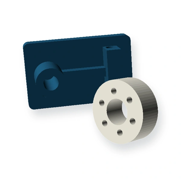
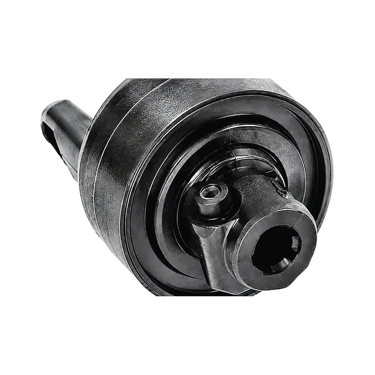
Custom molded parts
Drawing-specific housings, guides, covers, structural features and functional mechanisms.
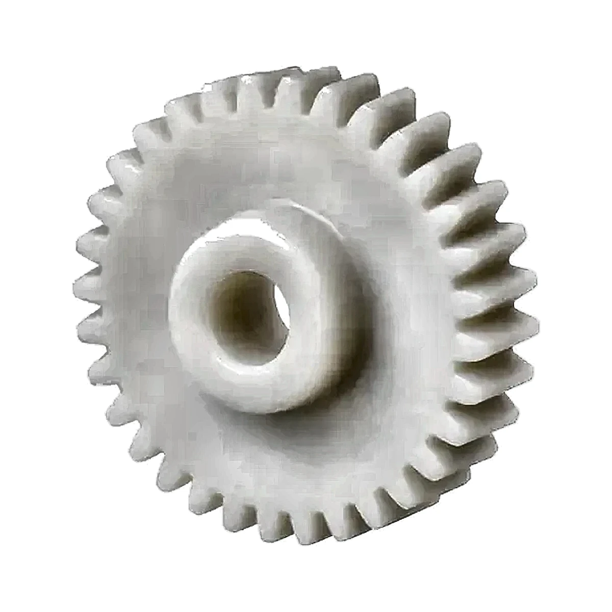
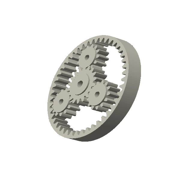
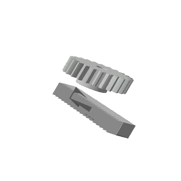
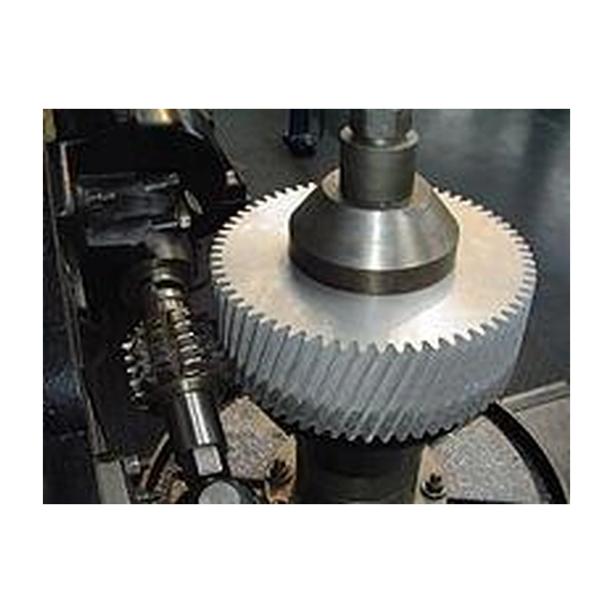
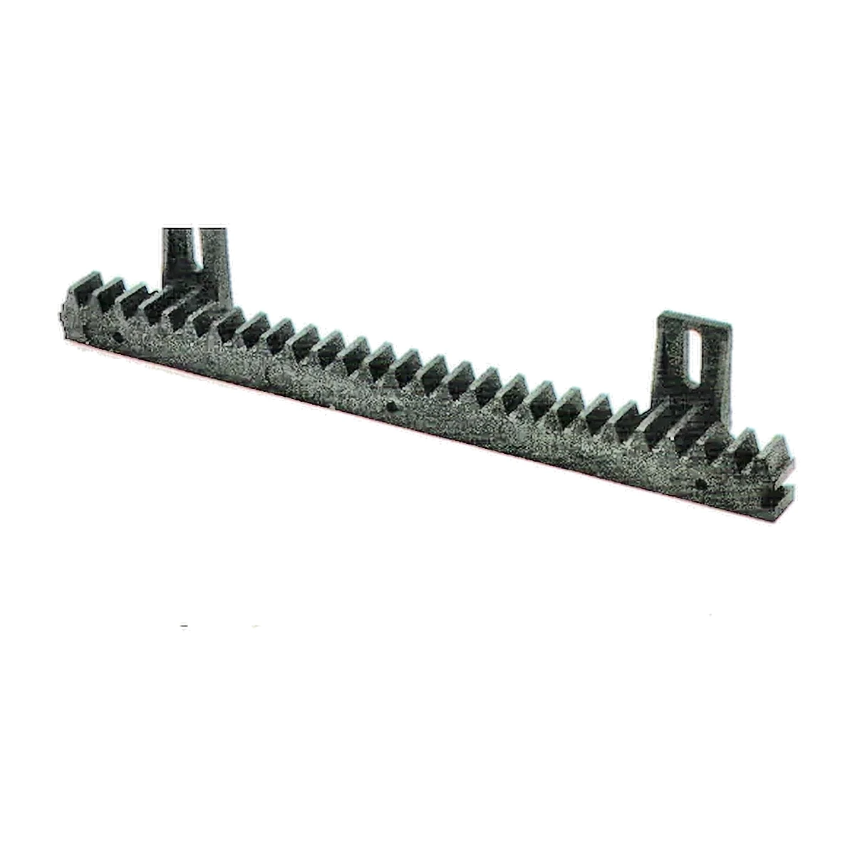
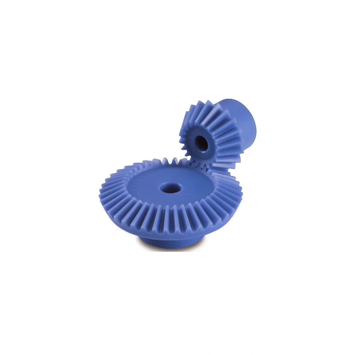
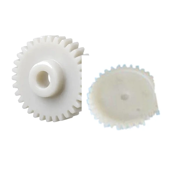
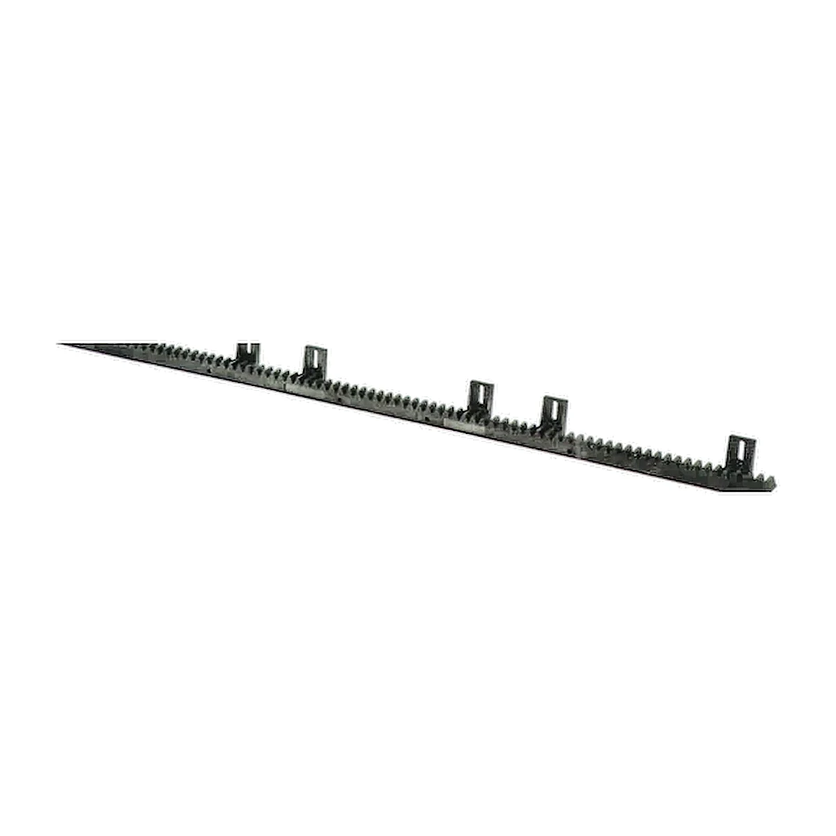
Plastic gears and racks
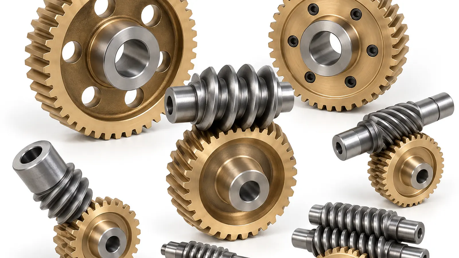
Spur, helical, bevel, worm, internal, planetary and linear-motion geometries.
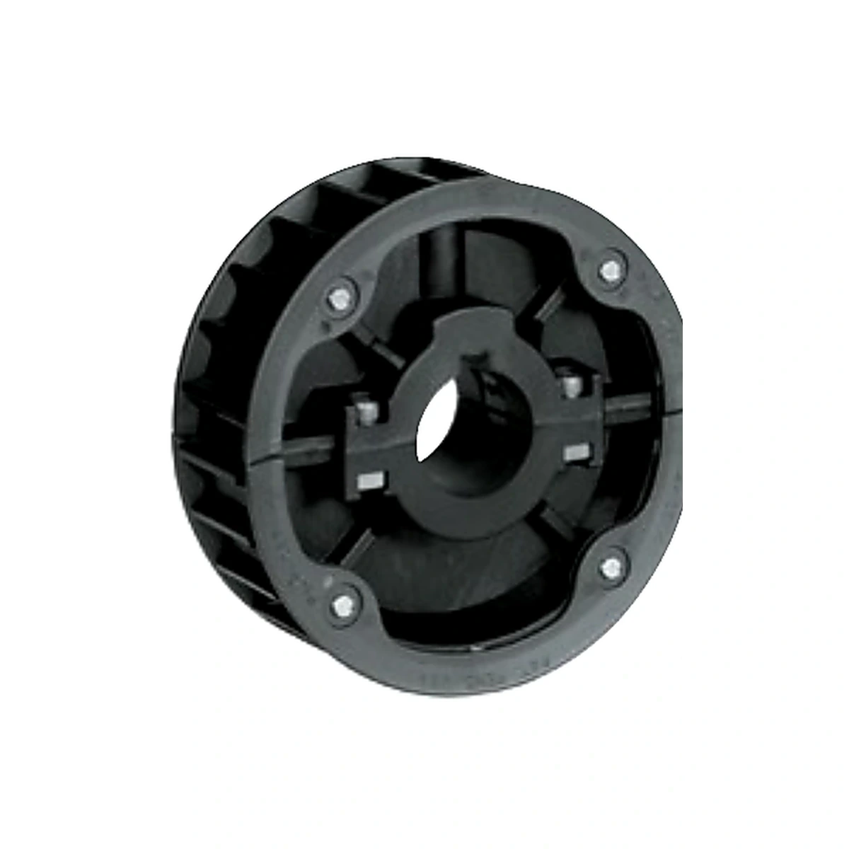
Plastic sprockets
Chain-drive components selected around chain series, tooth count, bore, hub and operating environment.
How the catalogue is structured
Use geometry as the first filter. A rack, bevel gear, internal gear, worm wheel and chain sprocket can all be made from engineering plastics, but they require different mating information and different assembly datums. The product-family pages therefore start from the mechanical interface instead of presenting a long resin list.
| Starting point | Open this route when… | Bring to the review |
|---|---|---|
| Standard geometry family | The component is recognizably a gear, rack or sprocket. | Tooth or chain system, mate, shaft interface and duty. |
| Custom molded component | The shape is defined by your assembly and cannot be selected from a standard family. | CAD, datums, wall map, inserts, loads, environment and volume. |
| Material-led replacement | A legacy metal or plastic part has a known field problem. | Existing sample, failure mode, mating surfaces and the requirement the new material must solve. |
Do not choose the manufacturing route too early
Injection molding is usually evaluated against annual demand, geometry, tool access, wall design and repeatability needs. Machining can be more practical for lower quantities, larger stock shapes, cast nylon components or projects where geometry is still changing. Some projects combine molding with a controlled secondary bore, datum or insert operation.
The correct route is the one that meets the functional drawing with acceptable process risk and total project cost. Send both quantity and revision status so tooling is not proposed for a design that is still moving.
How to compare product pages without guessing
Start with the interface that cannot move: shaft spacing, chain standard, rack pitch line, housing datums or assembly envelope. Then define the motion geometry and only after that compare materials and manufacturing routes. A familiar product name is not a complete specification. Two parts that look alike can require different tooth forms, bore fits, resin conditions or inspection methods.
Gear pages
Confirm module or DP, pressure angle, tooth count, face width, helix or bevel data where applicable, mating member, center distance or shaft angle, bore/hub details and the required backlash condition.
Rack and sprocket pages
For racks, define pitch geometry, mounting datum, length/joints and pinion mesh. For sprockets, begin with chain standard and pitch, then define tooth count, strand, bore, hub and shaft retention.
Custom molded parts
Identify wall sections, ribs, bosses, inserts, undercuts, cosmetic zones, sealing or bearing interfaces, gate/ejector restrictions and the dimensions that determine assembly function.
RFQ data that shortens the first engineering loop
A useful RFQ links the drawing revision to annual or batch quantity, material requirement or service conditions, mating components, critical dimensions, inspection expectations and any approved sample. Where a specification is still open, state the functional target rather than inserting a tight tolerance by default. That gives engineering room to choose a process and control plan that match the real risk.
For replacement components, send photographs only as context. Tooth geometry, shaft interfaces and datums still need dimensions or a sample that can be measured. For new molded parts, identify which surfaces may carry a gate, parting line or ejector witness and which surfaces are functionally or cosmetically restricted.
What makes a product record useful for sourcing
A product title is only a route into the engineering conversation. The quotation still needs the geometry that controls motion or fit, the mating interface, service environment, quantity and an acceptance method. For gears that means the tooth system and the bore-to-tooth relationship; for racks it means pitch line, length, joints and mounting datum; for sprockets it means the chain standard, tooth count, bore, hub and strand; for custom molded parts it means the CAD model, wall strategy, inserts and assembly datums.
Photographs are deliberately treated as visual references rather than dimensional evidence. A photograph can confirm the component family and show typical construction, but it cannot establish module, backlash, shaft fit or a critical molded dimension. The controlled drawing remains the production definition.
First: freeze the interface
Identify the surfaces, tooth geometry, shaft or mounting features that cannot move without changing the machine.
Second: define the duty
Add load, speed, reversing duty, temperature, moisture, chemicals, lubrication and the expected service cycle.
Third: agree acceptance
Mark CTQs, datums and functional checks so the sample review measures the features that actually control assembly performance.