
Compact mechanisms need predictable mesh and assembly fit
Office equipment and electromechanical modules often use small plastic gears because they can integrate hubs, cams and other features while keeping moving mass low. In these mechanisms, bore accuracy, concentricity, tooth quality and the relationship to the molded housing can be more important than headline torque.
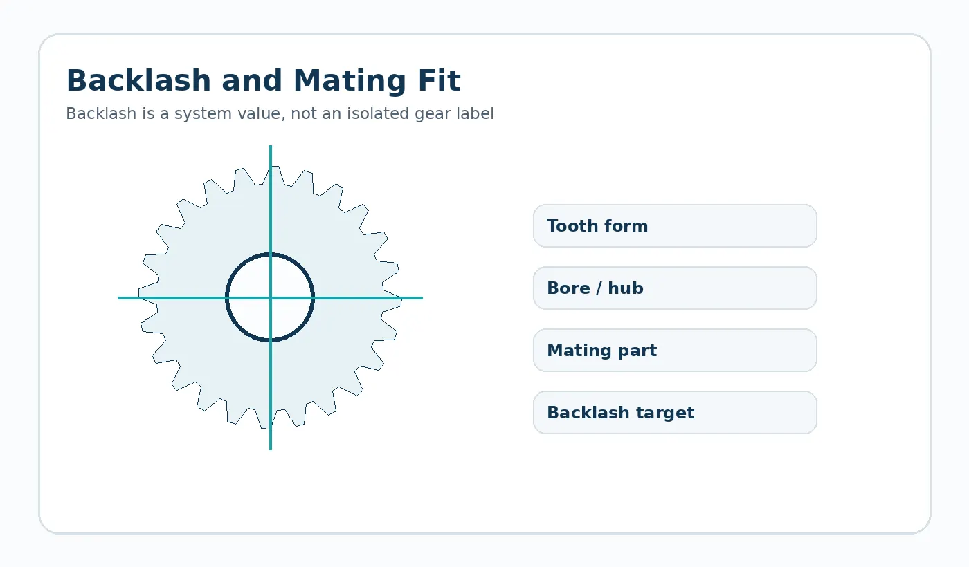
Share the complete gear train or at least the mating gear and center distance so tooth geometry and backlash are evaluated in context.
Useful design inputs
- Complete tooth count and module/DP information
- Bore, shaft and retention method
- Center distance and mating gear material
- Noise or positioning sensitivity
- Expected cycle count and duty pattern
- Assembly datums and housing constraints
Small gears still need a complete gear definition
Compact office mechanisms often contain several small gears in close proximity. Reverse engineering from outside diameter alone can misidentify module/DP or pressure angle, especially on worn parts. Tooth count, pitch system and center distance should be established together.
Molded hubs, cams or timing features may be integrated with the gear. Their angular relationship can be functional and should be dimensioned from the same datum system as the teeth.
Noise and feel
User-perceived noise can be sensitive to runout, tooth variation and housing resonance. Material choice contributes, but it is not the only control. Compare the complete gear train and housing support before changing resin to solve an acoustic issue.
Sample approval can include an assembled sound/feel check alongside gear measurements when the product requirement is genuinely perceptual.
Replacement information to capture
- All tooth counts in the local gear train
- Shaft center distances and bearing locations
- Bore/hub geometry and retention method
- Integrated cams, flags or timing features
- Expected cycle life and noise sensitivity
- Interchangeability with the existing housing
Validation plan for this application
Build the first-sample check around the machine interface. Confirm the mounting datums, mating part or chain, expected load direction, representative speed/cycle pattern and the service environment. Where position or backlash matters, measure the assembled mechanism after representative conditioning and cycling rather than approving only the free component.
Document any field constraint that is easy to miss on a component drawing: guard clearance, washdown chemical, nearby motor heat, unsupported rack span, reversing duty, or the bearing arrangement that fixes gear centers. These details often explain why a dimensionally acceptable part behaves differently in service.
Application acceptance rail
Before release, tie the component back to four controls: the operating duty, the mating interface, the environmental condition used for dimensional acceptance and the functional test that represents the real assembly. These controls prevent a nominally correct part from being approved under conditions that do not match service.
Duty
Peak and normal load, speed, reversals, cycle profile and expected service interval.
Interface
Mating geometry, support, alignment, fastener or shaft fit and the datum scheme used for measurement.
Acceptance
Conditioning state, critical dimensions, visual criteria and an assembly or motion check agreed before repeat production.
Information to include in the application review
Document the complete operating envelope rather than only nominal speed or load. Include starts and reversals, worst-case temperature and moisture, cleaning chemicals or lubricants, shaft and bearing support, the mating material, available installation space and any field-replacement constraint. If noise, backlash, wear or positional repeatability is the reason for the project, state that explicitly so the drawing and inspection plan can focus on the real problem.
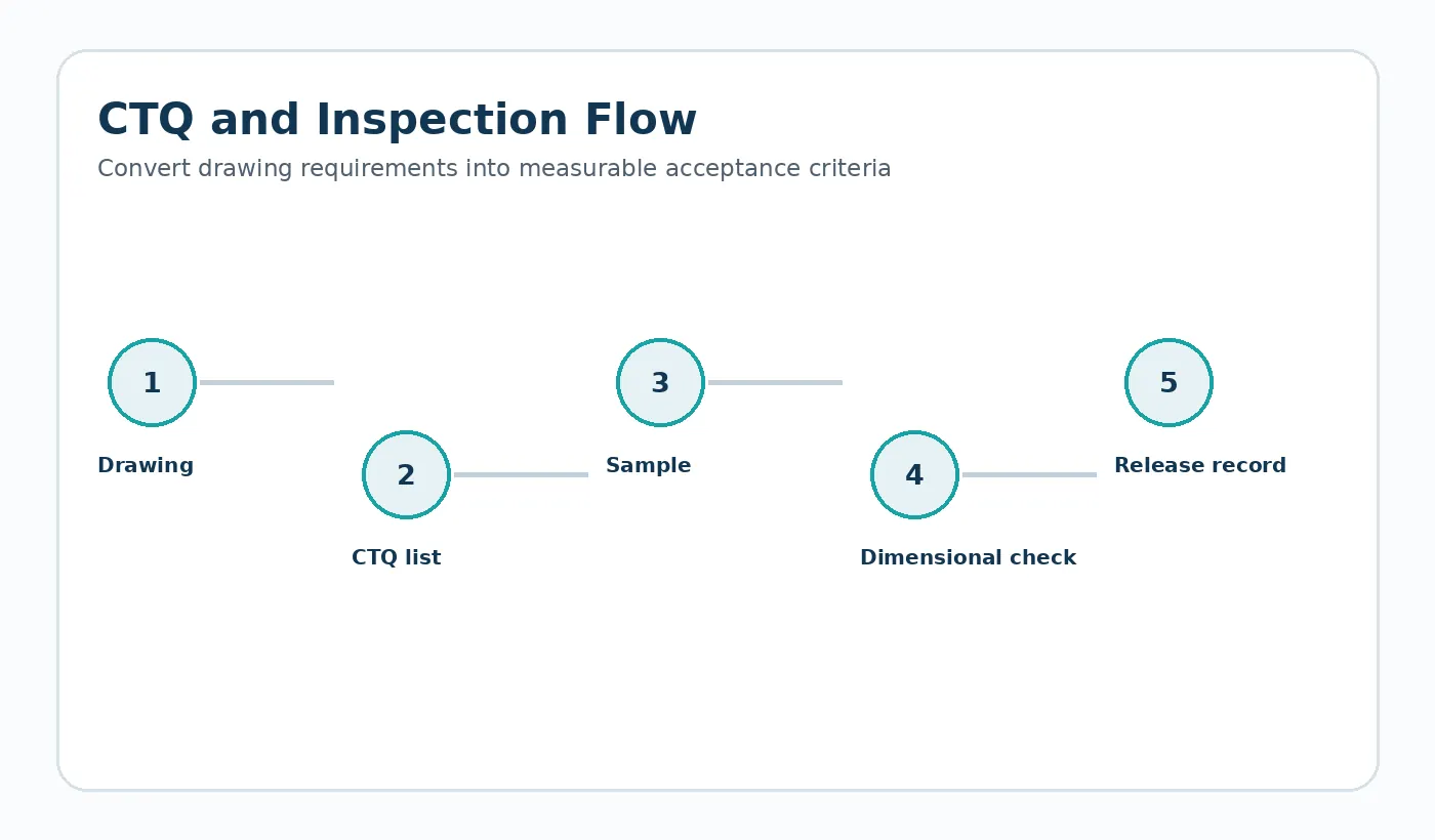
For first samples, define what will be checked in the component and what will be checked in the machine. A dimensional report verifies the drawing; an assembly or functional test verifies that the selected datums, fits and material condition produce the required behavior. Both are useful when the mechanism is sensitive to cumulative tolerances.

























