
ชิ้นส่วนพลาสติกในกลไกอัตโนมัติ
ระบบอัตโนมัติทางอุตสาหกรรมมักผสมผสานการเคลื่อนที่ซ้ำๆ การออกแบบที่กะทัดรัด และรอบการทำงานที่สั้น เฟืองพลาสติก ราง และตัวนำขึ้นรูปสามารถลดมวลและทำให้การรวมชิ้นส่วนง่ายขึ้น แต่การเลือกใช้ยังคงขึ้นอยู่กับภาระ ความเร็ว ความแข็งแรงของตัวรองรับ ความไวต่อการคลายตัว และสภาพแวดล้อมรอบเครื่องจักร
สำหรับกลไกการจัดตำแหน่งหรือการกำหนดตำแหน่ง ให้ระบุเส้นทางการเคลื่อนที่ทั้งหมดและรูปทรงเรขาคณิตของตัวขับที่เข้าคู่กัน แทนที่จะระบุเฉพาะเฟืองตัวใดตัวหนึ่งเพียงอย่างเดียว

จะกำหนดนิยามใดสำหรับหน้าที่การทำงานอัตโนมัติ
โปรไฟล์จักรยาน
การหมุนอย่างต่อเนื่อง การกำหนดตำแหน่ง การกลับทิศทาง และช่วงเวลาหยุดนิ่ง ส่งผลต่อความร้อนและการสึกหรอ
ข้อกำหนดด้านตำแหน่ง
การคลายตัว ความยืดหยุ่น และความคลาดเคลื่อนในการประกอบ สามารถส่งผลต่อความแม่นยำในการทำซ้ำได้
สภาพแวดล้อมของเครื่องจักร
ฝุ่นละออง สารหล่อลื่น สารทำความสะอาด และอุณหภูมิแวดล้อม อาจส่งผลต่อการเลือกใช้วัสดุ
การจัดทำดัชนี การกลับทิศทาง และการวางตำแหน่ง
อุปกรณ์อัตโนมัติสามารถเปลี่ยนทิศทางได้บ่อยครั้ง ซึ่งทำให้การคลายตัว การรองรับเพลา และความยืดหยุ่นของเฟืองปรากฏให้เห็นเป็นการเคลื่อนที่ที่สูญเสียไป คู่เฟืองที่ทำงานได้อย่างราบรื่นอาจแสดงพฤติกรรมที่แตกต่างกันออกไปในระหว่างการเร่งความเร็วอย่างรวดเร็วหรือการเปลี่ยนตำแหน่งซ้ำๆ
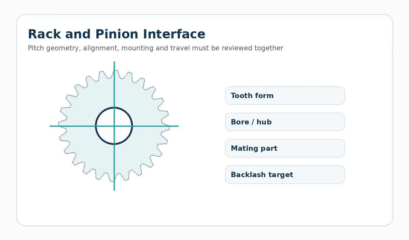
สำหรับแกนเฟืองแบบแร็คแอนด์พิเนียน ให้รวมถึงการรองรับแร็คและการปรับความสูงศูนย์กลางของเฟืองพิเนียน สำหรับชุดเฟืองแบบผสมหรือแบบดาวเคราะห์ ให้รวมถึงรูปทรงของแบริ่งและตัวยึดที่กำหนดตำแหน่งศูนย์กลางของเฟืองสัมพัทธ์
การเลือกใช้วัสดุภายในเซลล์อัตโนมัติ
ละอองน้ำมัน น้ำหล่อเย็น ฝุ่นละออง น้ำยาชะล้าง และความร้อนเฉพาะจุดจากมอเตอร์ อาจมีความสำคัญมากกว่าสภาพแวดล้อมภายในห้องโดยทั่วไป หากคาดว่าโพลิเมอร์จะทำงานได้โดยไม่ต้องใช้สารหล่อลื่น ควรระบุข้อกำหนดนั้นควบคู่ไปกับวัสดุที่ประกบกันและสภาพพื้นผิว
เมื่อการกำหนดตำแหน่งมีความสำคัญ ควรตรวจสอบกลไกทั้งหมดในช่วงอุณหภูมิที่คาดการณ์ไว้และหลังจากการทดสอบการทำงานที่เป็นตัวแทน แทนที่จะอนุมัติเฉพาะขนาดของเฟืองอิสระเท่านั้น
ชุดเอกสารขอใบเสนอราคาอัตโนมัติ
- ลักษณะการเคลื่อนที่: ความเร็ว การกลับทิศทาง ระยะเวลาหยุด และอัตราการทำงานต่อรอบ
- แรงบิด/ภาระ และแรงเฉื่อยที่ขับเคลื่อน
- การตอบโต้หรือเป้าหมายการวางตำแหน่ง
- การจับคู่เฟือง เพลา ตลับลูกปืน และรูปทรงของตัวเรือน
- อุณหภูมิ สารปนเปื้อน และสภาพของสารหล่อลื่น
- การทดสอบการยอมรับตัวอย่างในเครื่องจักรหรืออุปกรณ์จำลอง
Validation plan for this application
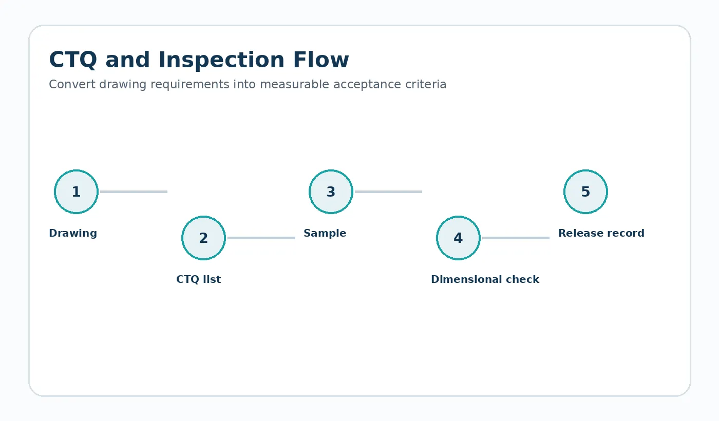
Build the first-sample check around the machine interface. Confirm the mounting datums, mating part or chain, expected load direction, representative speed/cycle pattern and the service environment. Where position or backlash matters, measure the assembled mechanism after representative conditioning and cycling rather than approving only the free component.
Document any field constraint that is easy to miss on a component drawing: guard clearance, washdown chemical, nearby motor heat, unsupported rack span, reversing duty, or the bearing arrangement that fixes gear centers. These details often explain why a dimensionally acceptable part behaves differently in service.
Application acceptance rail
Before release, tie the component back to four controls: the operating duty, the mating interface, the environmental condition used for dimensional acceptance and the functional test that represents the real assembly. These controls prevent a nominally correct part from being approved under conditions that do not match service.
Duty
Peak and normal load, speed, reversals, cycle profile and expected service interval.
Interface
Mating geometry, support, alignment, fastener or shaft fit and the datum scheme used for measurement.
Acceptance
Conditioning state, critical dimensions, visual criteria and an assembly or motion check agreed before repeat production.
Information to include in the application review
Document the complete operating envelope rather than only nominal speed or load. Include starts and reversals, worst-case temperature and moisture, cleaning chemicals or lubricants, shaft and bearing support, the mating material, available installation space and any field-replacement constraint. If noise, backlash, wear or positional repeatability is the reason for the project, state that explicitly so the drawing and inspection plan can focus on the real problem.
For first samples, define what will be checked in the component and what will be checked in the machine. A dimensional report verifies the drawing; an assembly or functional test verifies that the selected datums, fits and material condition produce the required behavior. Both are useful when the mechanism is sensitive to cumulative tolerances.

























