
மீண்டும் மீண்டும் செய்யக்கூடிய செயல்பாட்டு பாகங்களுக்கான ஊசி வார்ப்பு
ஊசி வார்ப்பு முறையானது சிக்கலான வடிவவியலையும் தொடர் உற்பத்தியையும் ஒரே செயல்முறையில் இணைக்க முடியும், ஆனால் முடிக்கப்பட்ட பாகமானது பெயரளவிலான CAD மாதிரியை விட அதிகமான காரணிகளால் வடிவமைக்கப்படுகிறது. சுவர் மாற்றங்கள், சாய்வு, வாயில் நிலை, பிரிதல், பிசின் சுருக்கம் மற்றும் குளிர்வித்தல் ஆகிய அனைத்தும் உற்பத்தித்திறனையும் பரிமாணப் பண்பையும் பாதிக்கின்றன.
உற்பத்திக்குத் தயாரான விலைக்குறிப்பு அறிக்கையானது, அலங்கார மேற்பரப்புகளைச் செயல்பாட்டு இடைமுகங்களிலிருந்து வேறுபடுத்திக் காட்ட வேண்டும் மற்றும் வார்ப்புக்குப் பிறகு கட்டுப்படுத்தப்பட்ட அளவீடு தேவைப்படும் பரிமாணங்களைக் கண்டறிய வேண்டும்.
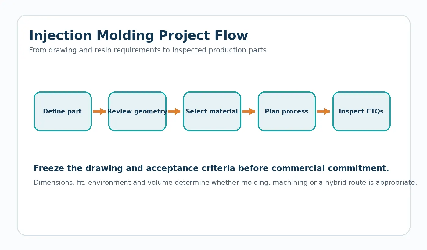
ஒரு நடைமுறை திட்ட வரிசை
| மேடை | முக்கிய பொறியியல் கேள்வி | பயனுள்ள உள்ளீடுகள் |
|---|---|---|
| வரைதல் மதிப்பாய்வு | இந்த வடிவவியலைத் தவிர்க்கக்கூடிய அபாயம் இன்றி நிரப்பவும், இறுக்கவும், குளிர்விக்கவும் மற்றும் வெளியேற்றவும் முடியுமா? | CAD, சுவர் பிரிவுகள், வரைவு, கீழ்வெட்டுகள், செருகல்கள், மேற்பரப்புத் தேவைகள் |
| பொருள் மதிப்பாய்வு | இந்த ரெசின், சுற்றுச்சூழலுக்கும் உற்பத்தி முறைக்கும் ஏற்றதா? | வெப்பநிலை, ஈரப்பதம், இரசாயன வெளிப்பாடு, சுமை, தேய்மான ஜோடி |
| கருவி மற்றும் மாதிரி எடுத்தல் | முக்கிய அம்சங்கள் எவ்வாறு உருவாக்கப்பட்டு சரிபார்க்கப்படும்? | வாயில்/பிரிப்புக் கருத்துரு, தரவுத்தளங்கள், மாதிரித் திட்டம், அளவீட்டு முறை |
| உற்பத்தி வெளியீடு | ஏற்றுக்கொள்ளக்கூடிய மீண்டும் வரும் பகுதி என்பதன் வரையறை என்ன? | அங்கீகரிக்கப்பட்ட மாதிரி, ஆய்வுத் திட்டம், பேக்கேஜிங் மற்றும் திருத்த நிலை |
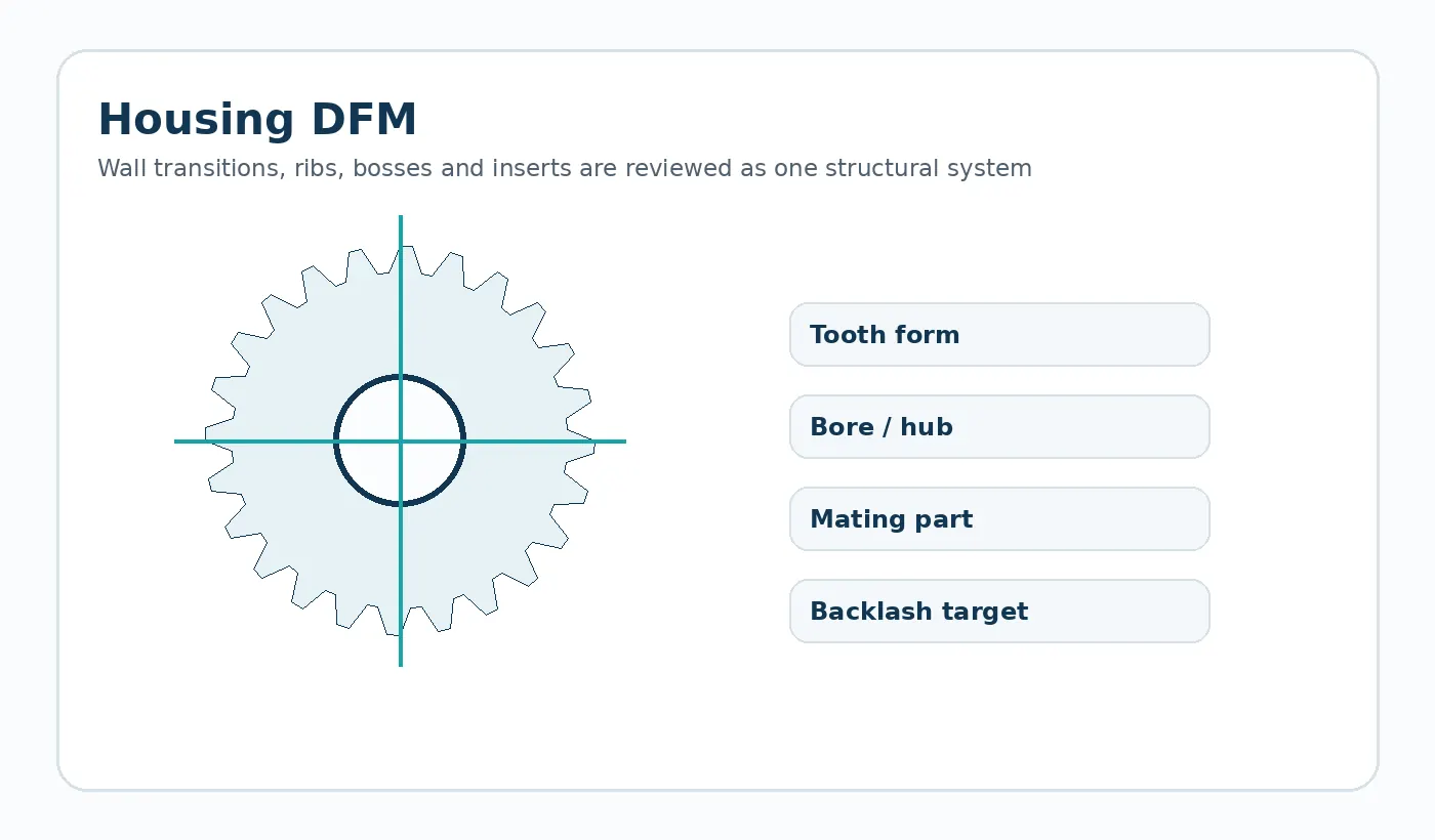
DFM கவனத்திற்குத் தகுதியான வடிவியல்
CAD-இல் பாலிமரின் பெயர் விடுபட்டிருப்பதால், செயல்பாட்டு வார்ப்புப் பாகங்கள் அரிதாகவே பழுதடைகின்றன. பெரும்பாலும், சுவர்கள், புடைப்புகள், துளைகள், செருகல்கள் மற்றும் அலங்கார மேற்பரப்புகள் ஆகியவை கருவியுடன் எவ்வாறு தொடர்பு கொள்கின்றன என்பதில்தான் ஆபத்து உள்ளது. ஒரு பயனுள்ள DFM ஆய்வு, தடித்த இடைமாற்றங்கள், கீழ்வெட்டுகள், அடைப்பான்கள், வெளியேற்றும் மேற்பரப்புகள் மற்றும் வாயில் அல்லது குளிரூட்டும் விருப்பங்களைக் கட்டுப்படுத்தும் அம்சங்களைக் கண்டறிகிறது.
ஒரு பரிமாணம் அசெம்பிளிக்கு முக்கியமானதாக இருக்கும்போது, அதை முக்கியமானதாக ஆக்கும் ஆதார உறவைக் காட்டவும். இது, ஒவ்வொரு பரிமாணத்திலும் சமமான முயற்சியைச் செலவிடுவதற்குப் பதிலாக, அச்சு வடிவமைப்பு சரியான இடைமுகத்தைப் பாதுகாக்க உதவுகிறது.
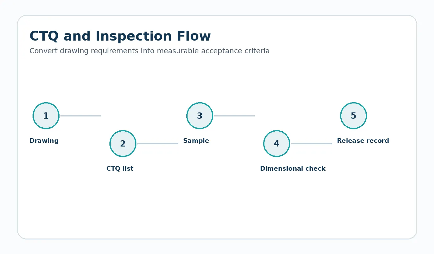
மாதிரி எடுத்தல், உற்பத்தி தொடர்பான கேள்விகளுக்குப் பதிலளிக்க வேண்டும்.
முதல் மாதிரிகள், ஒரு குழி நிரம்புகிறதா என்பதை மட்டும் சரிபார்க்கக் கூடாது. மீண்டும் செய்யப்படும் உற்பத்தியில் கண்காணிக்கப்பட வேண்டிய பண்புகளை மதிப்பாய்வு செய்யவும்: முக்கிய பரிமாணங்கள், செருகியின் நிலை, சமதளம், காட்சிப் பகுதிகள் மற்றும் செயல்பாட்டுப் பொருத்தம். பரிமாணங்கள் நிலைபெறுவதற்கு முன்பு ரெசினுக்குப் பதப்படுத்துதல் தேவைப்பட்டால், அந்த நிபந்தனையை ஒப்புதல் பதிவின் ஒரு பகுதியாக ஆக்குங்கள்.
மாதிரி எடுத்த பிறகு செய்யப்படும் மாற்றங்கள், வரைபடத் திருத்தத்துடன் இணைக்கப்பட வேண்டும். அவ்வாறு செய்வதன் மூலம், பௌதீக மாதிரி, CAD கோப்பு மற்றும் ஆய்வு அறிக்கை ஆகியவை வெவ்வேறு வடிவமைப்பு நிலைகளைக் குறிப்பிடும் ஒரு பொதுவான சிக்கல் தவிர்க்கப்படுகிறது.
வார்ப்புத் திட்டத்திற்கான RFQ தகவல்
- பொருத்தமான திருத்தத்துடன் கூடிய 2D வரைபடம் மற்றும் 3D CAD
- ரெசினின் தரம் (நிலையானதாக இருந்தால்), அல்லது மூலப்பொருள் தேர்வு திறந்திருந்தால் சேவை நிபந்தனைகள்.
- பகுதியின் நிறம், அமைப்பு மற்றும் புலப்படும்/அழகுபடுத்தும் பகுதிகள்
- செருகல்கள், இரண்டாம் நிலை இயந்திர வேலைப்பாடு, அச்சிடுதல் அல்லது ஒருங்கிணைப்பு செயல்பாடுகள்
- முன்மாதிரி/மாதிரி அளவு, உற்பத்தித் தொகுதி மற்றும் ஆண்டுத் தேவை
- தரத்திற்கு இன்றியமையாத பரிமாணங்கள் மற்றும் எதிர்பார்க்கப்படும் ஆய்வுச் சான்றுகள்
Tool-ready design means the functional definition is already stable
Before tool release, freeze the material family or its required properties, the assembly datums, critical dimensions, expected annual demand and any surfaces that constrain gate, parting line or ejector placement. Tool design can then support the product definition rather than compensate for an incomplete one.
Uniform wall intent, gradual transitions, appropriate draft and carefully proportioned ribs or bosses are useful DFM principles, but the final geometry still needs to reflect resin flow, tool access and the load path in the assembly. Thick local masses should be challenged because they can increase cooling variation and sink/void risk.
Sampling should close the loop between process and function
Measure the agreed CTQs under a defined conditioning state, record the molding condition used for the accepted sample, and then perform the functional fit or motion check. If a dimension is adjusted during sampling, update the controlled drawing or tool-correction record so production does not rely on undocumented trial history.
DFM checkpoints before a mold is released
Injection molding repeats geometry efficiently, so early design choices are repeated just as efficiently. Wall thickness should be deliberately managed instead of allowed to change abruptly around bosses or structural masses. Draft needs to be considered on surfaces that move against the tool during ejection. Ribs and gussets can add stiffness without turning the part into a thick solid section, while gate and ejector locations should be kept away from sealing, bearing or customer-facing surfaces where their witness can matter.
| DFM checkpoint | Review question | Release evidence |
|---|---|---|
| Wall strategy | Are thick-to-thin transitions, cores and local masses controlled for the chosen resin? | Section review on the current CAD model. |
| Draft and ejection | Can the part release without excessive drag, and are ejector witnesses placed on acceptable surfaces? | Tooling-direction review and marked cosmetic/functional zones. |
| Ribs and bosses | Do reinforcing features support the load without creating avoidable sink or difficult cooling? | Feature-by-feature DFM review. |
| Gate and weld lines | Will flow direction or weld-line location affect a loaded, cosmetic or sealing region? | Gate concept and, where justified, filling analysis. |
| CTQs | Which dimensions determine assembly, motion, sealing or insert position? | Ballooned drawing and agreed first-article plan. |
Tool release should therefore be a controlled engineering milestone. The latest CAD revision, resin, anticipated quantity, cosmetic zones, inserts, critical dimensions and first-sample acceptance method should all be identifiable before steel is cut. Changes after this point need to be evaluated for both part function and tooling impact.

























