
Injection molding for repeatable functional parts
Injection molding can combine complex geometry and repeat production in a single process, but the finished part is shaped by more than the nominal CAD model. Wall transitions, draft, gate position, parting, resin shrinkage and cooling all affect manufacturability and dimensional behavior.
A production-ready RFQ should distinguish cosmetic surfaces from functional interfaces and identify the dimensions that require controlled measurement after molding.
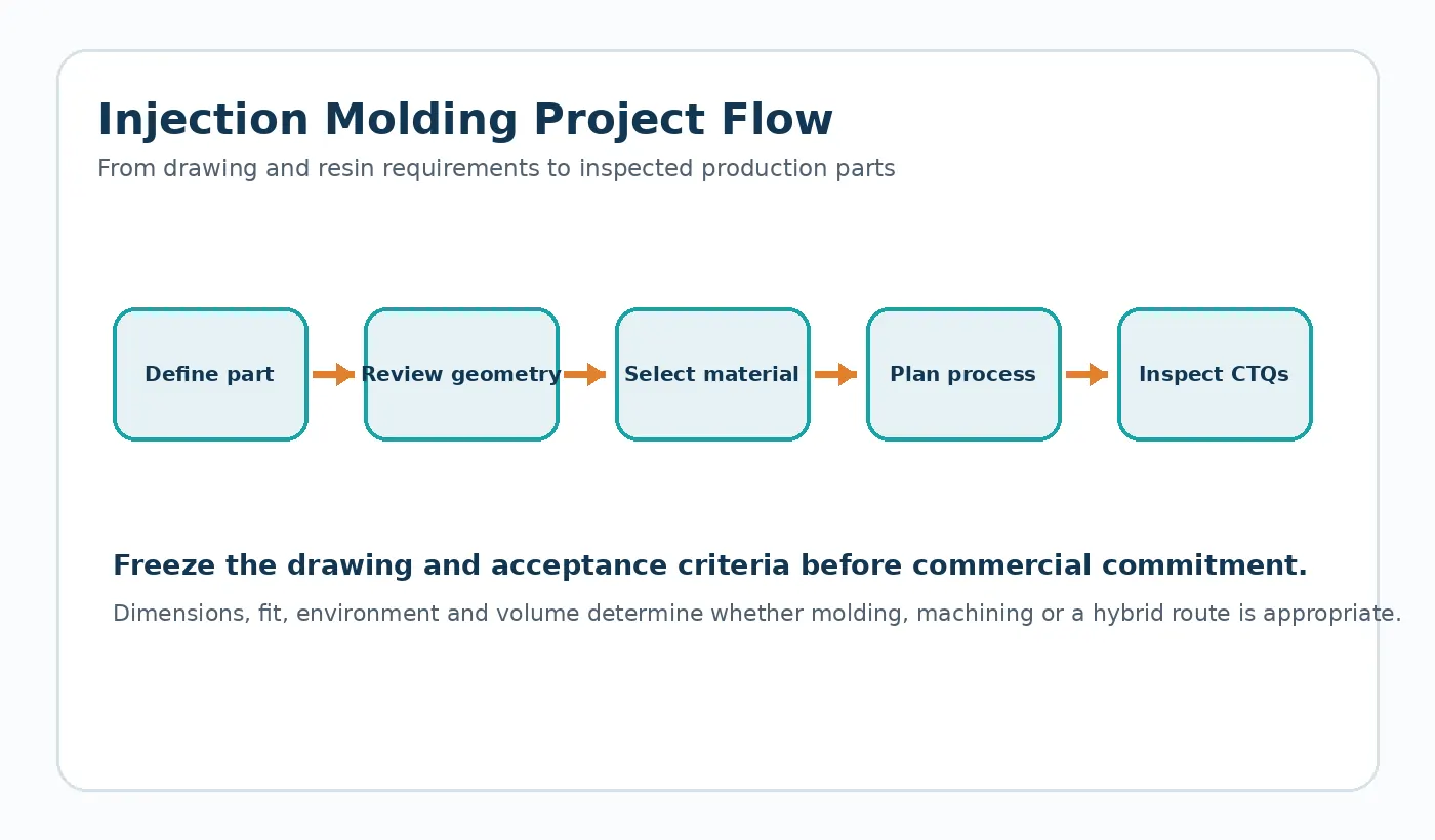
A practical project sequence
| Stage | Main engineering question | Useful inputs |
|---|---|---|
| Drawing review | Can the geometry fill, pack, cool and eject without avoidable risk? | CAD, wall sections, draft, undercuts, inserts, surface requirements |
| Material review | Does the resin suit the environment and the manufacturing route? | Temperature, moisture, chemical exposure, load, wear pair |
| Tooling and sampling | How will critical features be formed and checked? | Gate/parting concept, datums, sample plan, measurement method |
| Production release | What defines an acceptable repeat part? | Approved sample, inspection plan, packaging and revision level |
Geometry that deserves DFM attention
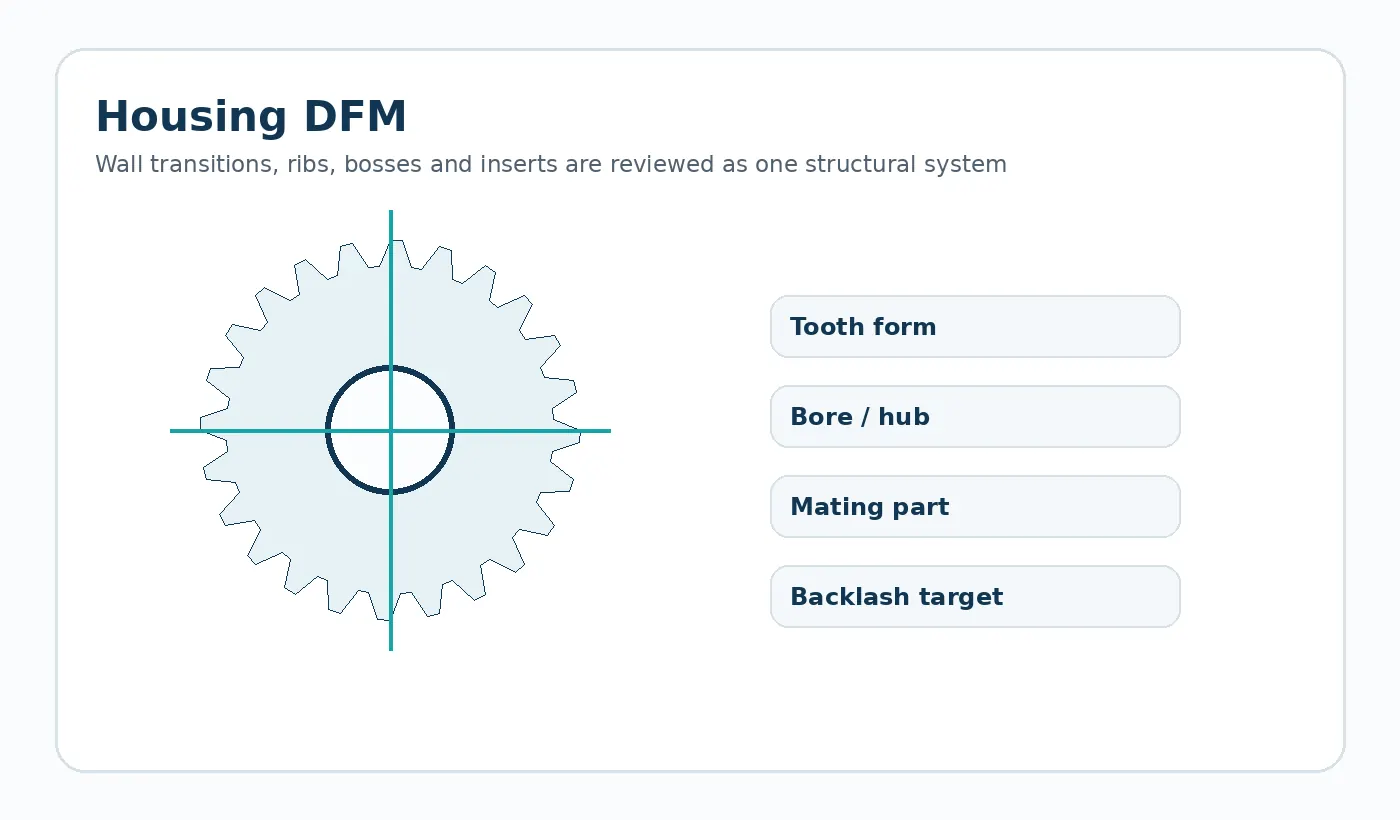
Functional molded parts rarely fail because the polymer name was missing from the CAD. More often, the risk sits in how walls, bosses, holes, inserts and cosmetic surfaces interact with the tool. A useful DFM review identifies thick transitions, undercuts, shutoffs, ejection surfaces and features that restrict gate or cooling options.
When a dimension is critical to assembly, show the datum relationship that makes it critical. This lets the mold concept protect the right interface rather than spending equal effort on every dimension.
Sampling should answer production questions
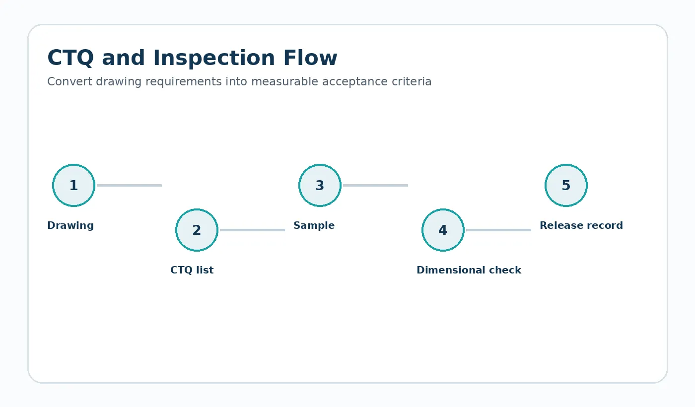
First samples should verify more than whether a cavity fills. Review the characteristics that will be monitored in repeat production: critical dimensions, insert position, flatness, visual zones and any functional fit. If the resin requires conditioning before dimensions stabilize, make that condition part of the approval record.
Changes after sampling should be linked to a drawing revision. That avoids a common problem in which the physical sample, CAD file and inspection report refer to different design states.
RFQ information for a molding project
- 2D drawing and 3D CAD with matching revision
- Resin grade if fixed, or service conditions if material selection is open
- Part colour, texture and visible/cosmetic zones
- Inserts, secondary machining, printing or assembly operations
- Prototype/sample quantity, production batch and annual demand
- Critical-to-quality dimensions and expected inspection evidence
Tool-ready design means the functional definition is already stable
Before tool release, freeze the material family or its required properties, the assembly datums, critical dimensions, expected annual demand and any surfaces that constrain gate, parting line or ejector placement. Tool design can then support the product definition rather than compensate for an incomplete one.
Uniform wall intent, gradual transitions, appropriate draft and carefully proportioned ribs or bosses are useful DFM principles, but the final geometry still needs to reflect resin flow, tool access and the load path in the assembly. Thick local masses should be challenged because they can increase cooling variation and sink/void risk.
Sampling should close the loop between process and function
Measure the agreed CTQs under a defined conditioning state, record the molding condition used for the accepted sample, and then perform the functional fit or motion check. If a dimension is adjusted during sampling, update the controlled drawing or tool-correction record so production does not rely on undocumented trial history.

























