Beskrivning
Plastic linear gear rack
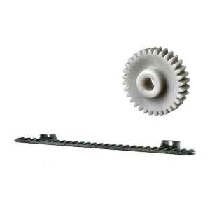
Plastic gear racks convert pinion rotation into linear travel. Tooth geometry must be coordinated with rack straightness, mounting support and any joints between rack lengths.
For molded rack segments, the gate and ejection concept should avoid distorting the tooth line or mounting face. For machined racks, stock straightness and fixture release matter. In both cases, the machine should provide a consistent backing datum instead of asking the rack to bridge large unsupported spans.
How to read the product photograph
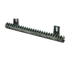
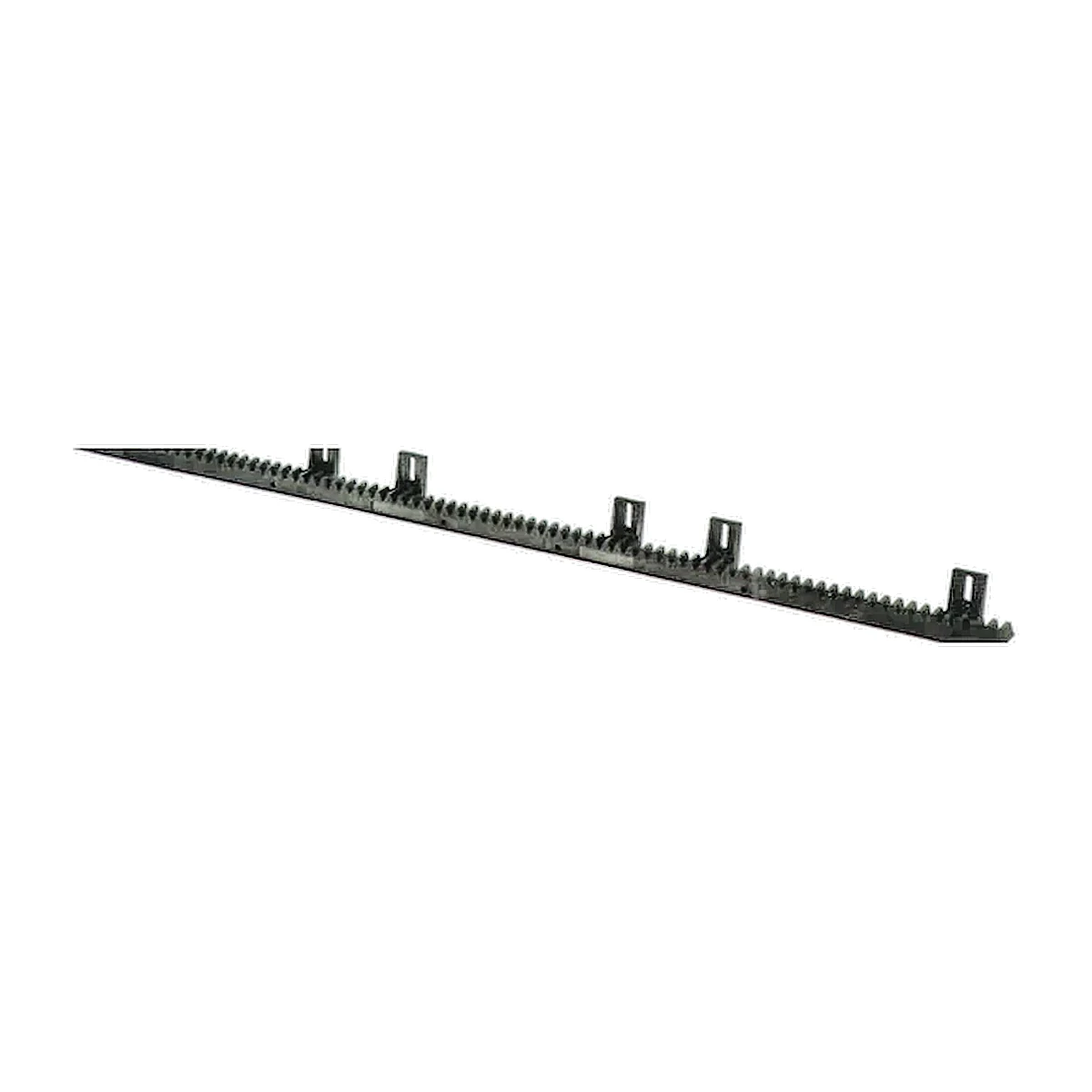
The main image is a photograph of a physical sample or representative component, not a dimensional definition. Resin colour, tooth count, bore or hub features, rack length, inserts and other details can change with the released drawing. Use the photograph to understand the product family; use the controlled drawing, mating interface and agreed inspection plan to manufacture and approve the part.
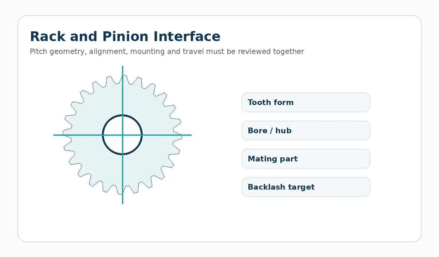
Geometry and interface inputs for Plastic Gear Racks
- Module/DP and pressure angle
- Rack length and cross-section
- Mounting-hole or backing-strip geometry
- Mating pinion and center height
- Travel, load and backlash requirement
Geometry reference: Straight rack / rack segment
Choosing the production route
Injection molding suits repeat modular lengths and integrated mounting features; machining can support long, low-volume or material-specific racks. The installation method should be selected with the process.
Packaged process reference: Machined or molded by geometry and quantity
Material direction: POM or nylon family by application
Application-specific design review
Bow, poor backing support or joint discontinuity can change backlash along the travel.
Typical use: Industrial automation, sliding mechanisms, adjustment systems and material handling. The final material and tolerance plan should be checked against the load path, mating components and environment in that assembly.
First sample and inspection focus
Measure pitch/geometry together with straightness and mounting datums. Validate the rack with the intended pinion across the required stroke where positioning is important.
Quotation decision: Module, pressure angle, length, mounting pattern, rack section, pinion match, pitch-line height and environmental conditions drive selection.

What to send for a Plastic Gear Racks quotation
Send the latest drawing or CAD model together with production quantity and the application conditions that affect fit, wear or dimensional stability. If the part replaces an existing component, identify the features that must remain interchangeable and any known field issue the new part is intended to solve.
- Controlled drawing revision and 3D model when available
- Mating-part or transmission geometry
- Material requirement or service environment
- Sample quantity, production batch and expected annual demand
- Critical dimensions and functional acceptance method
Engineering specification to freeze before manufacture
A production drawing should convert the application into measurable inputs. The table below is the minimum review set for this product family; add any assembly-specific datum, finish or acceptance requirement that changes function.
| Definition | What the supplier needs |
|---|---|
| Module or DP | Show the value, tolerance or functional requirement on the latest drawing. |
| Pressure angle | Show the value, tolerance or functional requirement on the latest drawing. |
| Rack length | Show the value, tolerance or functional requirement on the latest drawing. |
| Section / pitch-line height | Show the value, tolerance or functional requirement on the latest drawing. |
| Mounting pattern | Show the value, tolerance or functional requirement on the latest drawing. |
| Mating pinion | Show the value, tolerance or functional requirement on the latest drawing. |
| Straightness / alignment | Show the value, tolerance or functional requirement on the latest drawing. |
| Travel, load and environment | Show the value, tolerance or functional requirement on the latest drawing. |
Failure modes to prevent during design review
Common risks for this geometry include pitch-line misalignment; local rack bow or poor support; position error from environmental dimensional change. These are best addressed before the first sample by reviewing the complete mating interface, not by tightening every drawing tolerance.
Use tolerances selectively. Dimensions that establish the tooth mesh, chain engagement, shaft fit or assembly datum deserve explicit measurement methods; non-critical molded surfaces can often use a more practical general tolerance.
First-article and production acceptance
Agree the inspection condition, datums and measuring method before sampling. The first-article report should cover the drawing CTQs and then be paired with a functional check in the real assembly or a representative fixture. For gears and sprockets, that can include mesh or chain engagement, runout and bore relationship; for custom molded parts it can include fit, fastening and loaded features.
Production control should follow the same CTQs rather than replacing them with a long list of easy-to-measure cosmetic dimensions. If a bore, tooth, insert or mounting surface is secondary-machined, make clear which operation establishes the final datum.
Plastic Gear Racks FAQ
What should I send for quotation?
Send the latest 2D drawing and, where available, a 3D model. Add mating-part information, order quantity, service conditions and the features that control fit or motion. A sample is useful for replacement parts with uncertain legacy geometry.
How should the material be specified?
For POM or nylon projects, material family alone is not enough. Confirm the actual grade when it is mandatory, and state moisture, temperature, lubricant and mating material so dimensional and wear behavior can be reviewed.
How is the first sample approved?
Define the CTQs, inspection state and functional test before the sample is produced. Approval should confirm both measurable geometry and the behavior of the part in its intended interface.
Engineering decision brief for Plastic Gear Racks
Define the geometry
Straight rack / rack segment The quotation should use the drawing revision and mating interface as the controlling definition rather than an image alone.
Choose material by duty
POM or nylon family by application Material selection should be checked against load, speed, temperature, moisture or chemicals, lubrication and the required dimensional condition.
Freeze the production route
Machined or molded by geometry and quantity The route should be fixed only after quantity, tolerances, surface requirements and change risk are understood.
Agree acceptance
Module, pressure angle, length, mounting pattern, rack section, pinion match, pitch-line height and environmental conditions drive selection. First-article checks should therefore focus on the dimensions and functional interfaces that control the assembly.
Typical application context: Linear positioning, automatic doors, packaging, conveyor adjustment and industrial machine mechanisms.