
Descrição
Componentes da engrenagem solar, planetária e anular
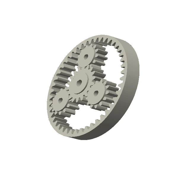
O sistema de engrenagens planetárias consiste em múltiplas engrenagens engrenadas simultaneamente. O número de dentes, a geometria do porta-satélites, as posições dos pinos planetários e a concentricidade da engrenagem anular devem ser mutuamente compatíveis antes que os componentes individuais sejam liberados.
Os conjuntos planetários exigem aritmética de contagem de dentes e geometria do porta-satélites compatíveis. Se vários planetas compartilharem a carga, suas posições de pino e a referência do anel devem ser controladas em conjunto. Porta-satélites moldados integrados podem reduzir a quantidade de peças, mas também adicionam a geometria do pino/rolamento à pilha de tolerâncias de moldagem.
How to read the product image
The main image is a representative technical redraw because the available raster source could not be enlarged without losing tooth-edge definition. It is used to communicate the product family and mechanical topology only. Tooth count, pitch/module, bore, hub, chain interface, material and all production dimensions are controlled by the released drawing.
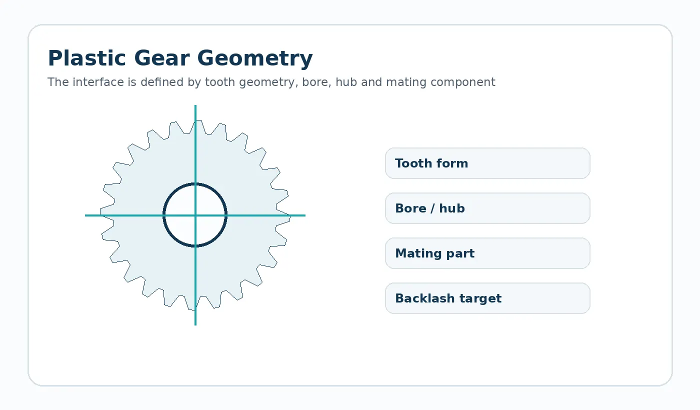
Geometria e entradas de interface para componentes de engrenagens planetárias moldados por injeção personalizados.
- Contagem de dentes solares, planetários e anulares
- Módulo/DP e ângulo de pressão
- Quantidade de planetas e círculo de pinos de suporte
- Furos, encaixes de pinos e montagem de anéis
- Faseamento, folga e caminho do torque
Referência geométrica: Sol, planeta, anel e componentes planetários relacionados.
Escolhendo a rota de produção
A moldagem pode integrar recursos de engrenagem e cubo para volumes de produção repetidos, enquanto a usinagem pode ser preferida durante o desenvolvimento ou para materiais e tamanhos específicos. Todo o processo deve ser analisado antes de selecionar uma rota.
Referência do processo empacotado: Moldagem por injeção para configurações personalizadas confirmadas
Direção do material: Nylon ou outro polímero de engenharia selecionado após revisão do projeto.
Revisão de projeto específica da aplicação
Pequenos erros de inclinação ou posição podem se acumular em vários planetas. A localização do pino portador e a distorção do anel podem, portanto, afetar a distribuição de carga e o ruído.
Uso típico: Redutores compactos, atuadores, mecanismos de escritório e acionamentos eletromecânicos. O plano final de materiais e tolerâncias deve ser verificado em relação ao caminho da carga, aos componentes de acoplamento e ao ambiente da montagem.
Primeiro foco na amostragem e inspeção
Verifique a geometria das engrenagens e os pontos de referência posicionais que localizam os planetas. Testes funcionais de montagem podem ser apropriados quando a distribuição de carga ou o ruído forem requisitos críticos.
Decisão sobre a cotação: Forneça a relação do sistema, o número de dentes, o módulo, a relação anel/solar/planetário, a geometria do porta-satélites, as interfaces furo/eixo, a velocidade, a carga e os requisitos de ciclo.
O que enviar para solicitar um orçamento de componentes de engrenagens planetárias moldados por injeção sob medida?
Envie o desenho ou modelo CAD mais recente, juntamente com a quantidade a ser produzida e as condições de aplicação que afetam o encaixe, o desgaste ou a estabilidade dimensional. Se a peça substituir um componente existente, identifique as características que devem permanecer intercambiáveis e qualquer problema conhecido em campo que a nova peça se destina a resolver.
- Revisão controlada do desenho e modelo 3D quando disponíveis.
- Geometria da peça de acoplamento ou transmissão
- Requisitos de material ou ambiente de serviço
- Quantidade de amostras, lote de produção e demanda anual prevista
- Dimensões críticas e método de aceitação funcional
Engineering specification to freeze before manufacture
A production drawing should convert the application into measurable inputs. The table below is the minimum review set for this product family; add any assembly-specific datum, finish or acceptance requirement that changes function.
| Definition | What the supplier needs |
|---|---|
| Sun tooth count | Show the value, tolerance or functional requirement on the latest drawing. |
| Planet tooth count | Show the value, tolerance or functional requirement on the latest drawing. |
| Ring tooth count | Show the value, tolerance or functional requirement on the latest drawing. |
| Module / pressure angle | Show the value, tolerance or functional requirement on the latest drawing. |
| Planet quantity and carrier pin locations | Show the value, tolerance or functional requirement on the latest drawing. |
| Ring mounting datum | Show the value, tolerance or functional requirement on the latest drawing. |
| Bore / shaft interfaces | Show the value, tolerance or functional requirement on the latest drawing. |
| Ratio, load, speed and backlash target | Show the value, tolerance or functional requirement on the latest drawing. |
Failure modes to prevent during design review
Common risks for this geometry include carrier pin position error; ring-to-sun eccentricity; unequal planet load sharing. These are best addressed before the first sample by reviewing the complete mating interface, not by tightening every drawing tolerance.
Use tolerances selectively. Dimensions that establish the tooth mesh, chain engagement, shaft fit or assembly datum deserve explicit measurement methods; non-critical molded surfaces can often use a more practical general tolerance.
First-article and production acceptance
Agree the inspection condition, datums and measuring method before sampling. The first-article report should cover the drawing CTQs and then be paired with a functional check in the real assembly or a representative fixture. For gears and sprockets, that can include mesh or chain engagement, runout and bore relationship; for custom molded parts it can include fit, fastening and loaded features.
Production control should follow the same CTQs rather than replacing them with a long list of easy-to-measure cosmetic dimensions. If a bore, tooth, insert or mounting surface is secondary-machined, make clear which operation establishes the final datum.
Engineering decision brief for Custom Injection Molded Planetary Gear Components
Define the geometry
Sun, planet, ring and related planetary components The quotation should use the drawing revision and mating interface as the controlling definition rather than an image alone.
Choose material by duty
Nylon or other selected engineering polymer after project review Material selection should be checked against load, speed, temperature, moisture or chemicals, lubrication and the required dimensional condition.
Freeze the production route
Injection molding for confirmed custom configurations The route should be fixed only after quantity, tolerances, surface requirements and change risk are understood.
Agree acceptance
Provide system ratio, tooth counts, module, ring/sun/planet relationship, carrier geometry, bore/shaft interfaces, speed, load and cycle requirements. First-article checks should therefore focus on the dimensions and functional interfaces that control the assembly.
Typical application context: Compact actuators, office equipment, appliances, robotics auxiliaries and custom motion systems.
Custom Injection Molded Planetary Gear Components FAQ
What should I send for quotation?
Send the latest 2D drawing and, where available, a 3D model. Add mating-part information, order quantity, service conditions and the features that control fit or motion. A sample is useful for replacement parts with uncertain legacy geometry.
How should the material be specified?
For POM or nylon projects, material family alone is not enough. Confirm the actual grade when it is mandatory, and state moisture, temperature, lubricant and mating material so dimensional and wear behavior can be reviewed.
How is the first sample approved?
Define the CTQs, inspection state and functional test before the sample is produced. Approval should confirm both measurable geometry and the behavior of the part in its intended interface.

























