
Decision first
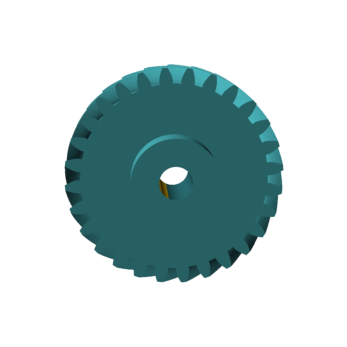
Helical gear drawings must make the helix convention unambiguous.
Helix angle, hand and the normal/transverse system affect mating compatibility. Helical gears also generate axial load that must be supported by the bearings and housing.
A drawing should never leave helix hand to interpretation from a 3D rendering. State it explicitly and define the reference system used for module and pressure angle. The mate then becomes easy to check. Because the helix creates axial force, the RFQ should also identify whether the shaft is supported by thrust-capable bearings or whether axial float could move the mesh during reversals.
Design inputs that change the answer
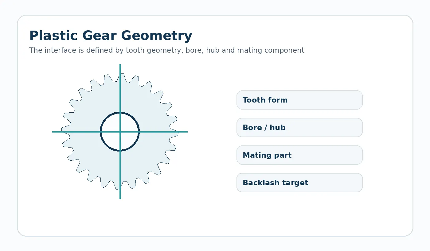
State tooth count, module/DP convention, pressure angle, helix angle/hand, face width, bore, center distance and mate.
Put these inputs on the controlled drawing, specification or RFQ attachment where possible. Keeping them out of informal message threads makes supplier comparisons and later revisions easier to manage.
Failure mode worth screening
A left/right hand error or mixed module convention can make an otherwise accurate part unusable.
Validation in the real assembly
Check the pair for correct hand, center distance, backlash and axial support before approving production.
For Plastic Helical Gear Design Inputs, keep the mating geometry and assembly datums in the same review as the component drawing. That is the most reliable way to connect part measurements to working performance.
RFQ handoff
Before requesting a price for plastic helical gear design inputs, identify the current drawing revision, production quantity, material constraint and the feature that most strongly affects function. Ask the supplier to flag any deviation from those inputs in the quotation so technical alternatives stay visible.

























