
What changes the engineering choice
Bevel gear design begins with the pair geometry and the intersecting shaft layout.
Ratio, shaft angle, pitch-cone geometry, face width and mounting distance determine how the teeth meet. Material flexibility does not remove the need for accurate shaft support.
Bevel gear contact is strongly influenced by where each gear sits along its shaft. A housing shoulder or bearing stack that shifts mounting distance can move contact toward an edge even if both gears are cut correctly. Include the axial locating features in the tolerance review. If the gear has a molded hub, also check how hub shrinkage or a press fit could alter the final mounted position.
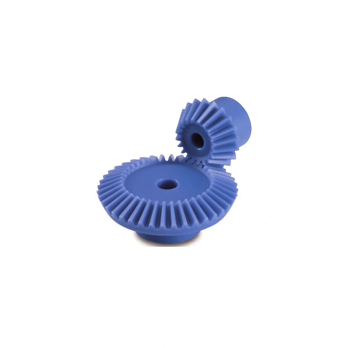
Drawing and application data
Provide both tooth counts, shaft angle, module/DP convention, pressure angle, face width, mounting distance, bore and mating gear material.
Put these inputs on the controlled drawing, specification or RFQ attachment where possible. Keeping them out of informal message threads makes supplier comparisons and later revisions easier to manage.
A common source of error
A correct tooth count pair can still run poorly when the assembly mounting distance or shaft angle is wrong.
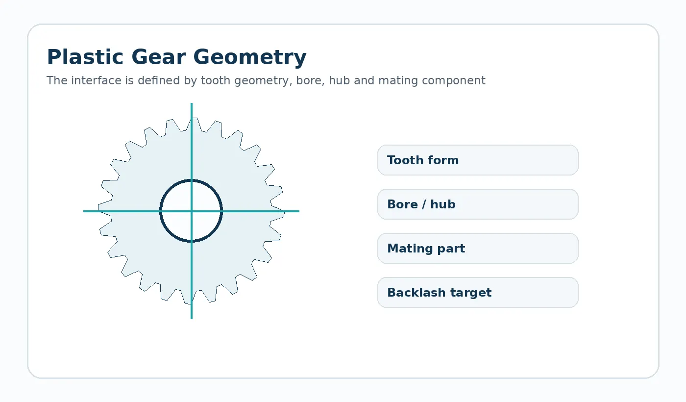
How to prove the design
Evaluate contact and backlash in the actual mounting arrangement during sample approval.
For Plastic Bevel Gear Design Inputs, keep the mating geometry and assembly datums in the same review as the component drawing. That is the most reliable way to connect part measurements to working performance.
Supplier brief
Before requesting a price for plastic bevel gear design inputs, identify the current drawing revision, production quantity, material constraint and the feature that most strongly affects function. Ask the supplier to flag any deviation from those inputs in the quotation so technical alternatives stay visible.
Practical design review for this decision
Treat the bevel gear as a pair. Shaft angle, tooth system, mounting distance, mate geometry and housing datums establish contact. A correct-looking single gear can still run poorly when the mount moves the contact toward a tooth edge.
Record the assumptions on the drawing or RFQ so the supplier can confirm them before quoting. When a value is unknown, identify it as an open engineering item rather than copying a generic catalogue number that may not match the assembly.
Verification worksheet
- Shaft angle and ratio
- Both tooth counts
- Module/DP and pressure angle
- Mounting distances
- Bore/hub and shaft support
- Backlash / contact acceptance
Use the first sample to close these points with both dimensional evidence and the relevant functional check. Any accepted deviation should be captured in the controlled revision before repeat production.

























