
Plastic components in automated mechanisms
Industrial automation often combines repetitive motion, compact packaging and short cycle times. Plastic gears, racks and molded guides can reduce mass and simplify component integration, but the selection still depends on load, speed, support stiffness, backlash sensitivity and the environment around the machine.
For indexing or positioning mechanisms, share the complete motion path and the mating drive geometry rather than specifying one gear in isolation.

What to define for automation duty
Cycle profile
Continuous rotation, indexing, reversals and dwell periods affect heat and wear.
Positioning requirement
Backlash, compliance and assembly tolerances can influence repeatability.
Machine environment
Dust, lubricants, cleaning agents and ambient temperature may change material choice.
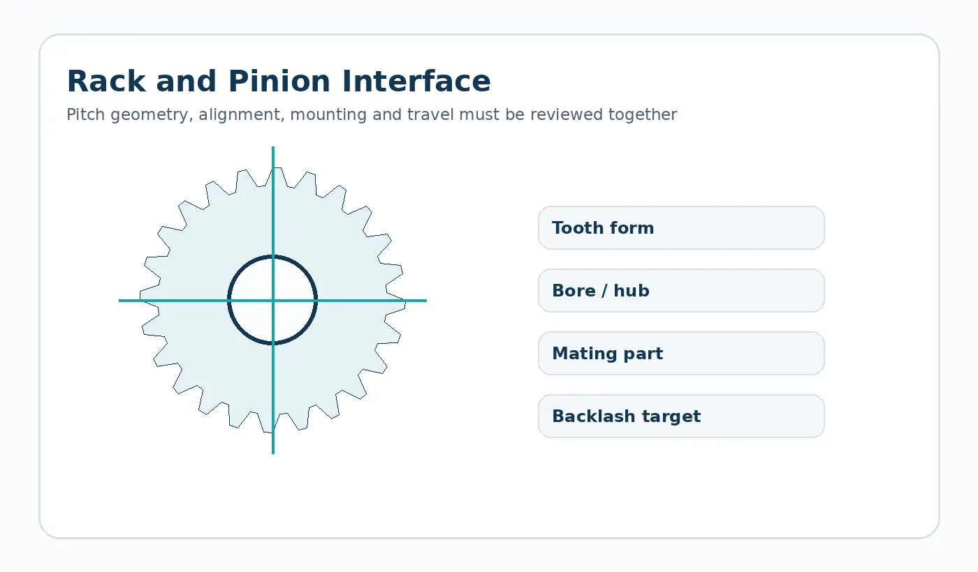
Indexing, reversals and positioning
Automated equipment can reverse direction frequently, which makes backlash, shaft support and gear compliance visible as lost motion. An acceptable steady-running gear pair may behave differently during rapid accelerations or repeated indexing.
For rack-and-pinion axes, include rack support and pinion center-height adjustment. For compound or planetary sets, include the bearing and carrier geometry that fixes the relative gear centers.
Material choice inside an automation cell
Oil mist, coolant, dust, washdown fluid and local heat from motors can be more important than the nominal room environment. If a polymer is expected to run without lubrication, that requirement should be stated together with the mating material and surface condition.
When positioning is critical, validate the complete mechanism over the expected temperature range and after representative cycling rather than approving only the free gear dimensions.
Automation RFQ package
- Motion profile: speed, reversals, dwell and cycle rate
- Torque/load and driven inertia
- Backlash or positioning target
- Mating gears, shafts, bearings and housing geometry
- Temperature, contaminants and lubricant condition
- Sample acceptance test in the machine or representative fixture
Validation plan for this application
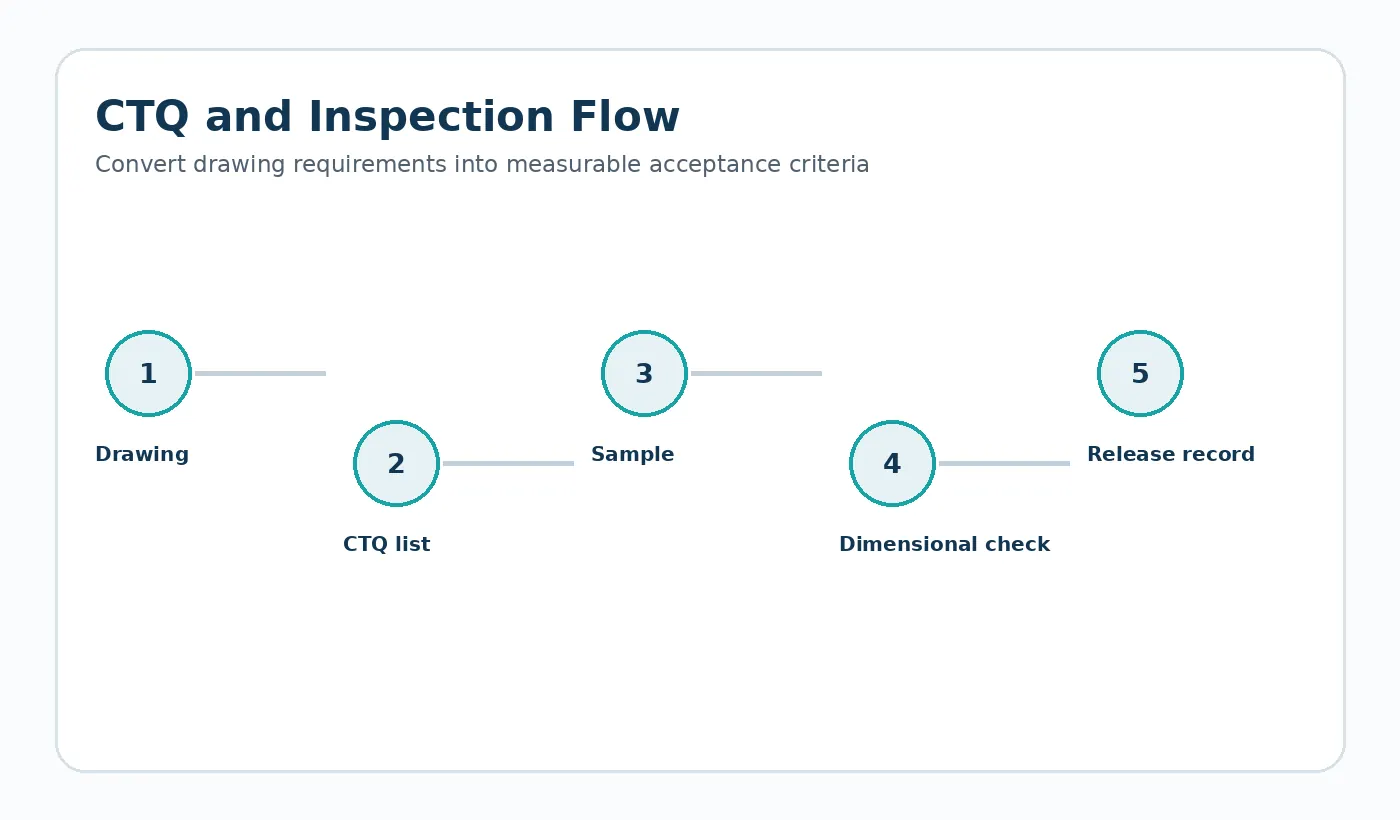
Build the first-sample check around the machine interface. Confirm the mounting datums, mating part or chain, expected load direction, representative speed/cycle pattern and the service environment. Where position or backlash matters, measure the assembled mechanism after representative conditioning and cycling rather than approving only the free component.
Document any field constraint that is easy to miss on a component drawing: guard clearance, washdown chemical, nearby motor heat, unsupported rack span, reversing duty, or the bearing arrangement that fixes gear centers. These details often explain why a dimensionally acceptable part behaves differently in service.
Application acceptance rail
Before release, tie the component back to four controls: the operating duty, the mating interface, the environmental condition used for dimensional acceptance and the functional test that represents the real assembly. These controls prevent a nominally correct part from being approved under conditions that do not match service.
Kewajipan
Peak and normal load, speed, reversals, cycle profile and expected service interval.
Antara muka
Mating geometry, support, alignment, fastener or shaft fit and the datum scheme used for measurement.
Penerimaan
Conditioning state, critical dimensions, visual criteria and an assembly or motion check agreed before repeat production.
Information to include in the application review
Document the complete operating envelope rather than only nominal speed or load. Include starts and reversals, worst-case temperature and moisture, cleaning chemicals or lubricants, shaft and bearing support, the mating material, available installation space and any field-replacement constraint. If noise, backlash, wear or positional repeatability is the reason for the project, state that explicitly so the drawing and inspection plan can focus on the real problem.
For first samples, define what will be checked in the component and what will be checked in the machine. A dimensional report verifies the drawing; an assembly or functional test verifies that the selected datums, fits and material condition produce the required behavior. Both are useful when the mechanism is sensitive to cumulative tolerances.

























