설명
Custom molded components from CAD
Use this route for drawing-specific parts where wall sections, ribs, bosses, inserts, undercuts, cosmetic surfaces and functional interfaces must be reviewed before tooling.
A useful molding drawing also indicates where gate vestige, ejector marks or parting witness are acceptable. These are manufacturing features, but they can become functional problems when placed on sealing surfaces, sliding rails or visible customer-facing areas. If inserts are used, show the insertion direction and the loads that pass through them.
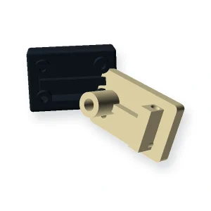
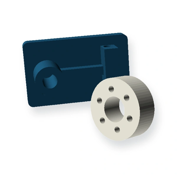
How to read the product photograph
The main image is a photograph of a physical sample or representative component, not a dimensional definition. Resin colour, tooth count, bore or hub features, rack length, inserts and other details can change with the released drawing. Use the photograph to understand the product family; use the controlled drawing, mating interface and agreed inspection plan to manufacture and approve the part.
Geometry and interface inputs for Custom Injection Molded Plastic Parts
- Latest 2D drawing and 3D CAD
- Critical dimensions and datum scheme
- Resin requirement or service environment
- Batch/annual quantity and sample needs
- Inserts, textures, colours and secondary operations
Geometry reference: Drawing-based functional component
Choosing the production route
Injection molding is most effective after geometry is stable enough to justify tooling. Early design revisions can be explored by machining or additive prototypes when the objective is fit or assembly learning rather than final-process validation.
Packaged process reference: Injection molding
Material direction: Project-specific thermoplastic; confirm resin grade at RFQ
Application-specific design review
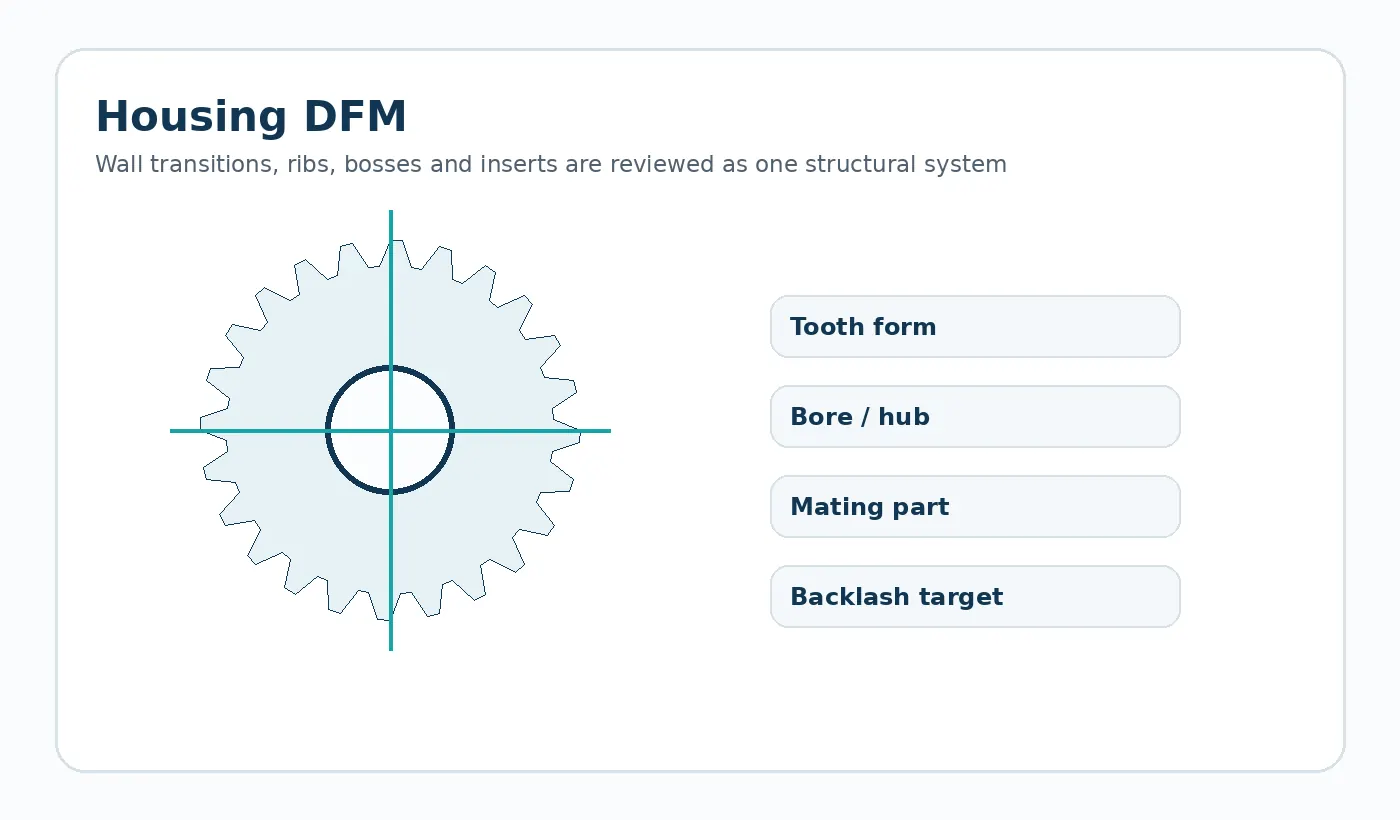
Uneven wall transitions, poorly supported bosses, difficult ejection features and unprioritized tight tolerances can create avoidable tooling or dimensional risk.
Typical use: Automation housings, guides, covers, brackets, electromechanical parts and integrated plastic mechanisms. The final material and tolerance plan should be checked against the load path, mating components and environment in that assembly.
First sample and inspection focus
Define the dimensions that control assembly, insert position, flatness or sealing. Cosmetic acceptance should be described separately from dimensional acceptance.
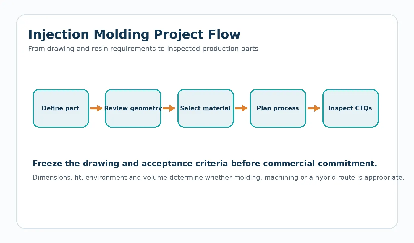
Quotation decision: Freeze CAD, critical dimensions, resin requirements, annual demand and visible/cosmetic zones before tooling decisions.
What to send for a Custom Injection Molded Plastic Parts quotation
Send the latest drawing or CAD model together with production quantity and the application conditions that affect fit, wear or dimensional stability. If the part replaces an existing component, identify the features that must remain interchangeable and any known field issue the new part is intended to solve.
- Controlled drawing revision and 3D model when available
- Mating-part or transmission geometry
- Material requirement or service environment
- Sample quantity, production batch and expected annual demand
- Critical dimensions and functional acceptance method
Engineering specification to freeze before manufacture
A production drawing should convert the application into measurable inputs. The table below is the minimum review set for this product family; add any assembly-specific datum, finish or acceptance requirement that changes function.
| Definition | What the supplier needs |
|---|---|
| Controlled drawing / CAD revision | Show the value, tolerance or functional requirement on the latest drawing. |
| Functional datums and mating interfaces | Show the value, tolerance or functional requirement on the latest drawing. |
| Nominal wall and wall transitions | Show the value, tolerance or functional requirement on the latest drawing. |
| Ribs, bosses, inserts and fastening loads | Show the value, tolerance or functional requirement on the latest drawing. |
| Resin grade or service requirements | Show the value, tolerance or functional requirement on the latest drawing. |
| Gate / ejector / cosmetic restrictions | Show the value, tolerance or functional requirement on the latest drawing. |
| Critical dimensions and inspection method | Show the value, tolerance or functional requirement on the latest drawing. |
| Prototype, batch and annual quantity | Show the value, tolerance or functional requirement on the latest drawing. |
Failure modes to prevent during design review
Common risks for this geometry include sink or warp around thick transitions; insert or boss loading without a clear load path; ambiguous datums that make inspection inconsistent. These are best addressed before the first sample by reviewing the complete mating interface, not by tightening every drawing tolerance.
Use tolerances selectively. Dimensions that establish the tooth mesh, chain engagement, shaft fit or assembly datum deserve explicit measurement methods; non-critical molded surfaces can often use a more practical general tolerance.
First-article and production acceptance
Agree the inspection condition, datums and measuring method before sampling. The first-article report should cover the drawing CTQs and then be paired with a functional check in the real assembly or a representative fixture. For gears and sprockets, that can include mesh or chain engagement, runout and bore relationship; for custom molded parts it can include fit, fastening and loaded features.
Production control should follow the same CTQs rather than replacing them with a long list of easy-to-measure cosmetic dimensions. If a bore, tooth, insert or mounting surface is secondary-machined, make clear which operation establishes the final datum.
Engineering decision brief for Custom Injection Molded Plastic Parts
Define the geometry
Drawing-specific molded geometry with walls, ribs, bosses, holes, inserts, clips and assembly interfaces defined by the application. The quotation should use the drawing revision and mating interface as the controlling definition rather than an image alone.
Choose material by duty
Project-specific thermoplastic; confirm resin grade at RFQ Material selection should be checked against load, speed, temperature, moisture or chemicals, lubrication and the required dimensional condition.
Freeze the production route
Injection molding The route should be fixed only after quantity, tolerances, surface requirements and change risk are understood.
Agree acceptance
Freeze CAD, critical dimensions, resin requirements, annual demand and visible/cosmetic zones before tooling decisions. First-article checks should therefore focus on the dimensions and functional interfaces that control the assembly.
Typical application context: Automation mechanisms, equipment subassemblies, housings, guides, moving components and other drawing-led industrial parts.
Custom Injection Molded Plastic Parts FAQ
What should I send for quotation?
Send the latest 2D drawing and, where available, a 3D model. Add mating-part information, order quantity, service conditions and the features that control fit or motion. A sample is useful for replacement parts with uncertain legacy geometry.
How should the material be specified?
Material should be selected from service temperature, chemicals or moisture, stiffness, wear, dimensional requirements and production route. A preferred grade can be quoted, but the application requirements should be supplied with it.
How is the first sample approved?
Define the CTQs, inspection state and functional test before the sample is produced. Approval should confirm both measurable geometry and the behavior of the part in its intended interface.