Description
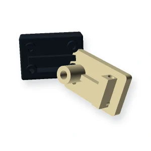
Custom molded components from CAD
Use this route for drawing-specific parts where wall sections, ribs, bosses, inserts, undercuts, cosmetic surfaces and functional interfaces must be reviewed before tooling.
A useful molding drawing also indicates where gate vestige, ejector marks or parting witness are acceptable. These are manufacturing features, but they can become functional problems when placed on sealing surfaces, sliding rails or visible customer-facing areas. If inserts are used, show the insertion direction and the loads that pass through them.
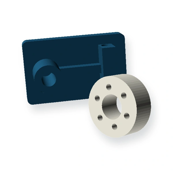
Geometry and interface inputs for Custom Injection Molded Plastic Parts
- Latest 2D drawing and 3D CAD
- Critical dimensions and datum scheme
- Resin requirement or service environment
- Batch/annual quantity and sample needs
- Inserts, textures, colours and secondary operations
Geometry reference: Drawing-based functional component
Choosing the production route
Injection molding is most effective after geometry is stable enough to justify tooling. Early design revisions can be explored by machining or additive prototypes when the objective is fit or assembly learning rather than final-process validation.
Packaged process reference: Injection molding
Material direction: Project-specific thermoplastic; confirm resin grade at RFQ
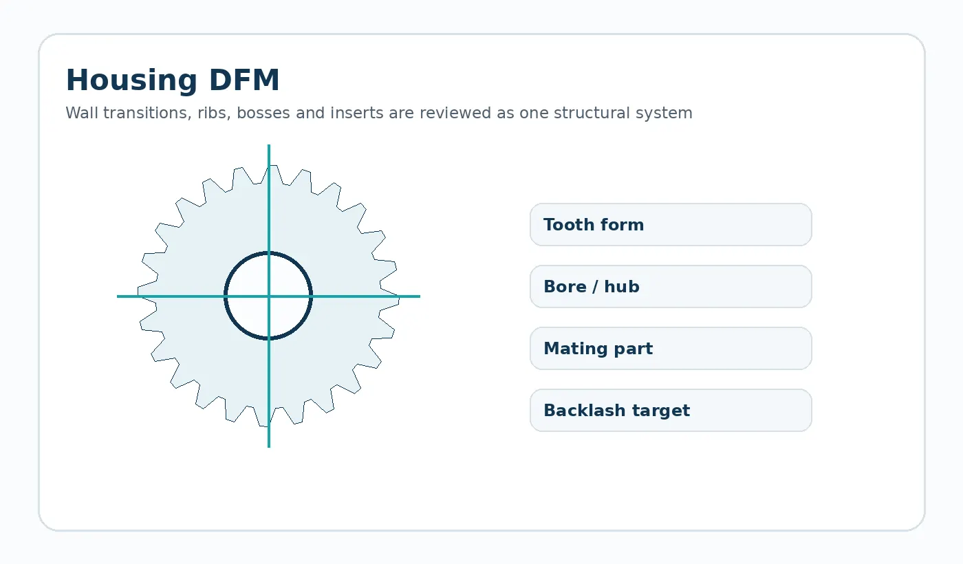
Application-specific design review
Uneven wall transitions, poorly supported bosses, difficult ejection features and unprioritized tight tolerances can create avoidable tooling or dimensional risk.
Typical use: Automation housings, guides, covers, brackets, electromechanical parts and integrated plastic mechanisms. The final material and tolerance plan should be checked against the load path, mating components and environment in that assembly.
First sample and inspection focus
Define the dimensions that control assembly, insert position, flatness or sealing. Cosmetic acceptance should be described separately from dimensional acceptance.
Quotation decision: Freeze CAD, critical dimensions, resin requirements, annual demand and visible/cosmetic zones before tooling decisions.
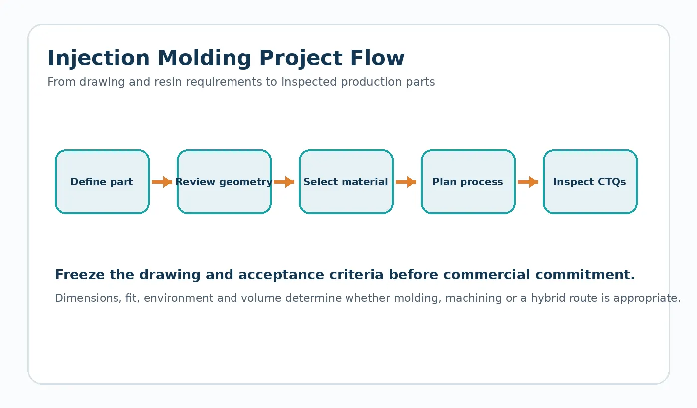
What to send for a Custom Injection Molded Plastic Parts quotation
Send the latest drawing or CAD model together with production quantity and the application conditions that affect fit, wear or dimensional stability. If the part replaces an existing component, identify the features that must remain interchangeable and any known field issue the new part is intended to solve.
- Controlled drawing revision and 3D model when available
- Mating-part or transmission geometry
- Material requirement or service environment
- Sample quantity, production batch and expected annual demand
- Critical dimensions and functional acceptance method