
Integrated plastic parts for appliance and electromechanical assemblies
Appliance mechanisms can combine gears, housings, levers, guides and snap-fit features in a constrained space. Material choice therefore has to account for both mechanical duty and the surrounding thermal, electrical, moisture or chemical environment.
When several functions are integrated into one molded component, identify which interfaces control assembly and which surfaces are cosmetic. This helps keep tolerances focused on the areas that affect the mechanism.

Design review focus
Integrated features
Review ribs, bosses, clips, inserts, bearing seats and gear features as one molded geometry.
Environment
Temperature, moisture, detergents, oils or electrical requirements can narrow resin choices.
Assembly sequence
Fasteners, press fits, snap fits and mating shafts should be included in the tolerance review.
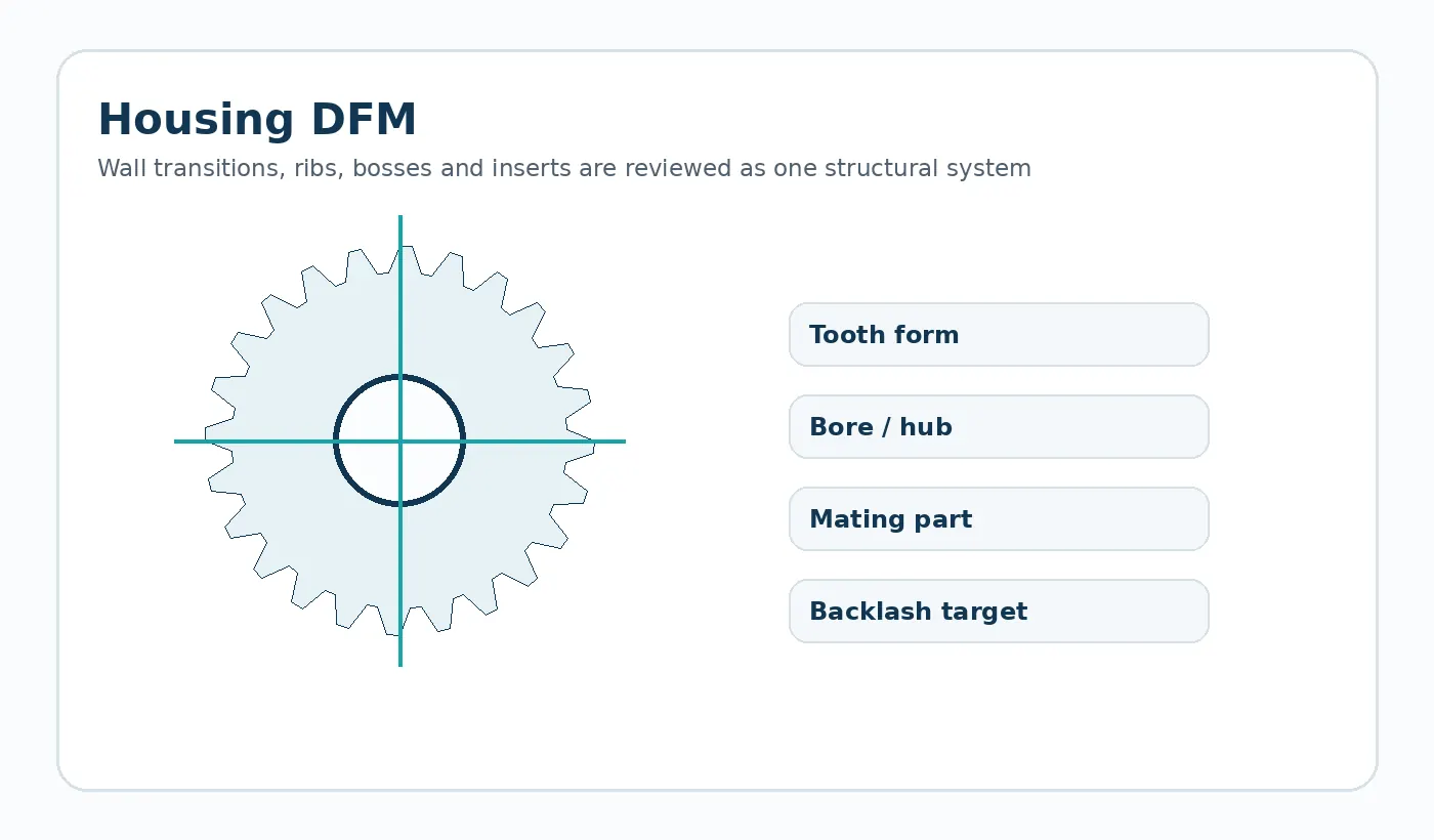
Integrated molded features create coupled tolerances
An appliance component may contain a gear, bearing seat, snap feature and mounting boss in one molding. Each function shares the same shrinkage and warpage behavior, so local fixes can affect another interface. A thicker boss may improve screw strength but move a nearby bearing seat; a gate change may improve filling but shift fibre orientation in a reinforced housing.
Review the full component with the assembly sequence visible. This keeps DFM changes connected to function.
Service environment
Heat from motors or heaters, occasional moisture, cleaning agents and long dwell under load can matter in appliances. For snap fits or spring-like features, creep over time may be as important as initial assembly force.
List the continuous and short-term temperature conditions and identify any chemical exposure. If a resin is mandated by an electrical or flammability requirement, include the exact requirement in the RFQ.
Electromechanical RFQ inputs
- Assembly drawing showing mating parts
- Integrated gear, snap, insert and fastener features
- Thermal and moisture environment
- Electrical/flame/chemical requirements where applicable
- Critical fits and installation sequence
- Production quantity and cosmetic zones
Validation plan for this application
Build the first-sample check around the machine interface. Confirm the mounting datums, mating part or chain, expected load direction, representative speed/cycle pattern and the service environment. Where position or backlash matters, measure the assembled mechanism after representative conditioning and cycling rather than approving only the free component.
Document any field constraint that is easy to miss on a component drawing: guard clearance, washdown chemical, nearby motor heat, unsupported rack span, reversing duty, or the bearing arrangement that fixes gear centers. These details often explain why a dimensionally acceptable part behaves differently in service.

























