
Frame the problem correctly
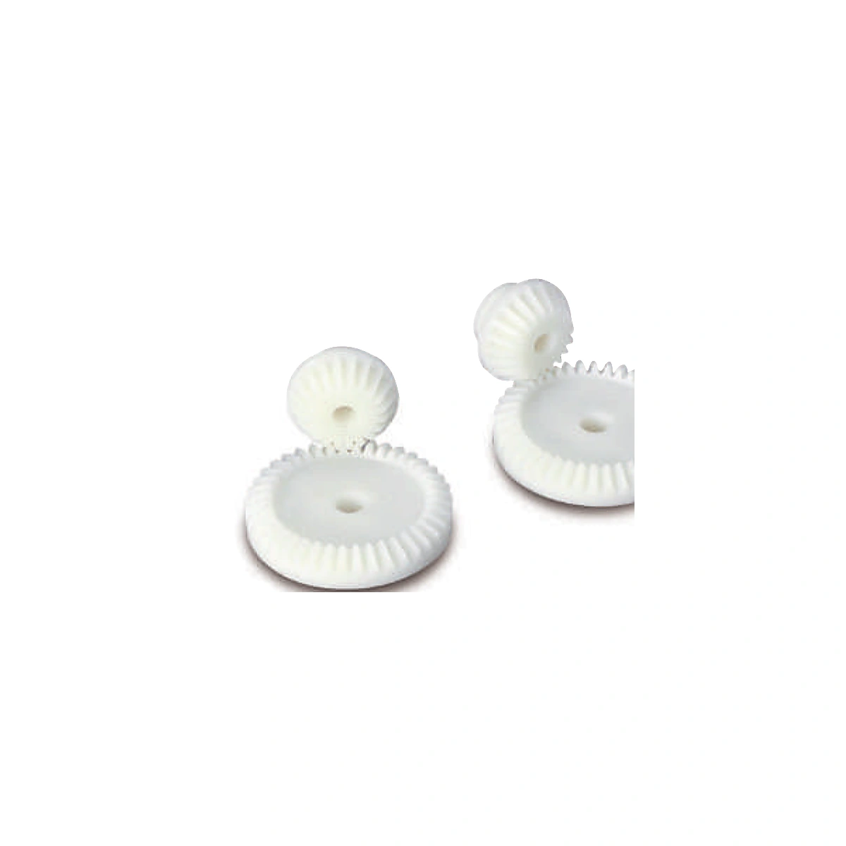
An injection molded bevel gear should be selected around its mating gear, moldability and assembly datums.
Bevel teeth, hub geometry and wall sections need to be compatible with filling, cooling and ejection. The bore-to-tooth relationship is especially important because it controls the assembled pitch-cone position.
Mold flow into a bevel gear is not symmetric when the hub, spokes or integrated features break the geometry. Gate choice can influence weld lines and shrinkage, while the conical tooth form needs clean ejection. A production review should therefore cover the entire component, not just whether the teeth can be machined into the mold. Sample approval should include the installed pair at the intended mounting distance.
Geometry, material and duty
Confirm ratio, shaft angle, tooth form, resin, bore/hub geometry, mounting distance, quantity and acceptance method.
Put these inputs on the controlled drawing, specification or RFQ attachment where possible. Keeping them out of informal message threads makes supplier comparisons and later revisions easier to manage.
Where the risk appears
Treating the bevel gear as a standalone catalog item can hide the mounting geometry that determines tooth contact.
First-sample evidence
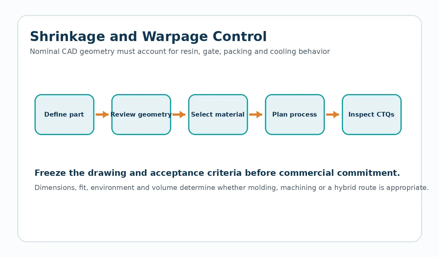
Use first-article dimensional checks plus a representative gear-pair mesh evaluation.
For Injection Molded Bevel Gear Selection, close the DFM loop by updating the controlled CAD/drawing and sample plan. A recommendation that never reaches the released revision cannot be inspected consistently in production.
Production-release notes
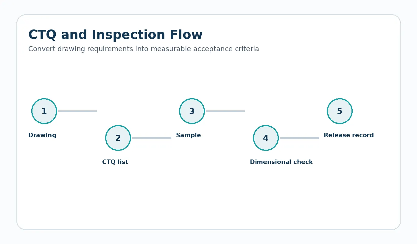
Before requesting a price for injection molded bevel gear selection, identify the current drawing revision, production quantity, material constraint and the feature that most strongly affects function. Ask the supplier to flag any deviation from those inputs in the quotation so technical alternatives stay visible.
Practical design review for this decision
Treat the bevel gear as a pair. Shaft angle, tooth system, mounting distance, mate geometry and housing datums establish contact. A correct-looking single gear can still run poorly when the mount moves the contact toward a tooth edge.
Record the assumptions on the drawing or RFQ so the supplier can confirm them before quoting. When a value is unknown, identify it as an open engineering item rather than copying a generic catalogue number that may not match the assembly.
Verification worksheet
- Shaft angle and ratio
- Both tooth counts
- Module/DP and pressure angle
- Mounting distances
- Bore/hub and shaft support
- Backlash / contact acceptance
Use the first sample to close these points with both dimensional evidence and the relevant functional check. Any accepted deviation should be captured in the controlled revision before repeat production.

























