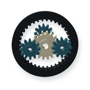
Engranajes moldeados por inyección
Gear geometry developed for molded productionMolded gear projects need tooth design, hub/wall transitions, gate strategy, shrinkage and acceptance criteria to be reviewed as one system.Injection molding can repeat complex gear-and-hub geometry efficiently, but the tooth form is connected to a molded body that shrinks and cools as a whole. Hub/web proportions, gate position and resin grade therefore influence bore-to-tooth relationships and runout.What to define before opening an RFQModule or DP, pressure angle and tooth countMaterial grade and shrinkage behaviorBore, hub and adjacent wall geometryGate/parting constraints and ejectabilityRunout, tooth quality and functional mesh checksA molded gear drawing should make the functional datum scheme and acceptance method explicit. If secondary machining is planned, show which surfaces remain as-molded and which become the final reference after machining.How to use this categoryThe product cards below are linked to the live WooCommerce catalogue for Injection Molded Gears. Open the closest geometry first, then compare its RFQ guidance against your drawing. If no listed product matches the interface, use the custom component route rather than forcing the part into the wrong family.Selection data that separates a usable quote from a generic quoteInputRequired definitionGear geometry and tooth systemDefine on the drawing or project brief before supplier review.Expected annual volumeDefine on the drawing or project brief before supplier review.Resin grade and shrinkage dataDefine on the drawing or project brief before supplier review.Gate / weld-line restrictionsDefine on the drawing or project brief before supplier review.Bore and hub interfaceDefine on the drawing or project brief before supplier review.Critical tooth / runout measurementsDefine on the drawing or project brief before supplier review.Conditioning state for inspectionDefine on the drawing or project brief before supplier review.Functional mesh acceptanceDefine on the drawing or project brief before supplier review.Injection molding becomes attractive when geometry and volume justify tooling and the design can accommodate process-driven dimensional behavior. It should not be assumed simply because the part is plastic.Engineering review before releaseThe review needs both gear geometry and molding geometry. Hub thickness, gate location, wall transitions and fiber orientation can influence roundness, tooth-to-bore relationship and repeatability.Where a material family is not yet fixed, provide the operating temperature, moisture or chemical exposure, mating material, lubrication condition and expected production volume. Those inputs let the process and resin be reviewed together instead of treating the polymer name as the complete design.RFQ and first-sample pathStart with the closest product below, then send the controlled drawing, mating-part information and the dimensions that are critical to function. For a replacement component, include a sample or measured interface data if the original tooth or chain standard is uncertain.Compare materialsCustom engineeringSend an RFQ
Mostrando el único resultado