Description
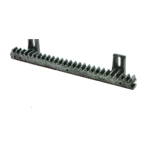
MC nylon machined gear family
MC nylon is commonly considered for larger machined gears and wear components. Its moisture response and temperature-dependent dimensions should be part of the fit and backlash calculation.
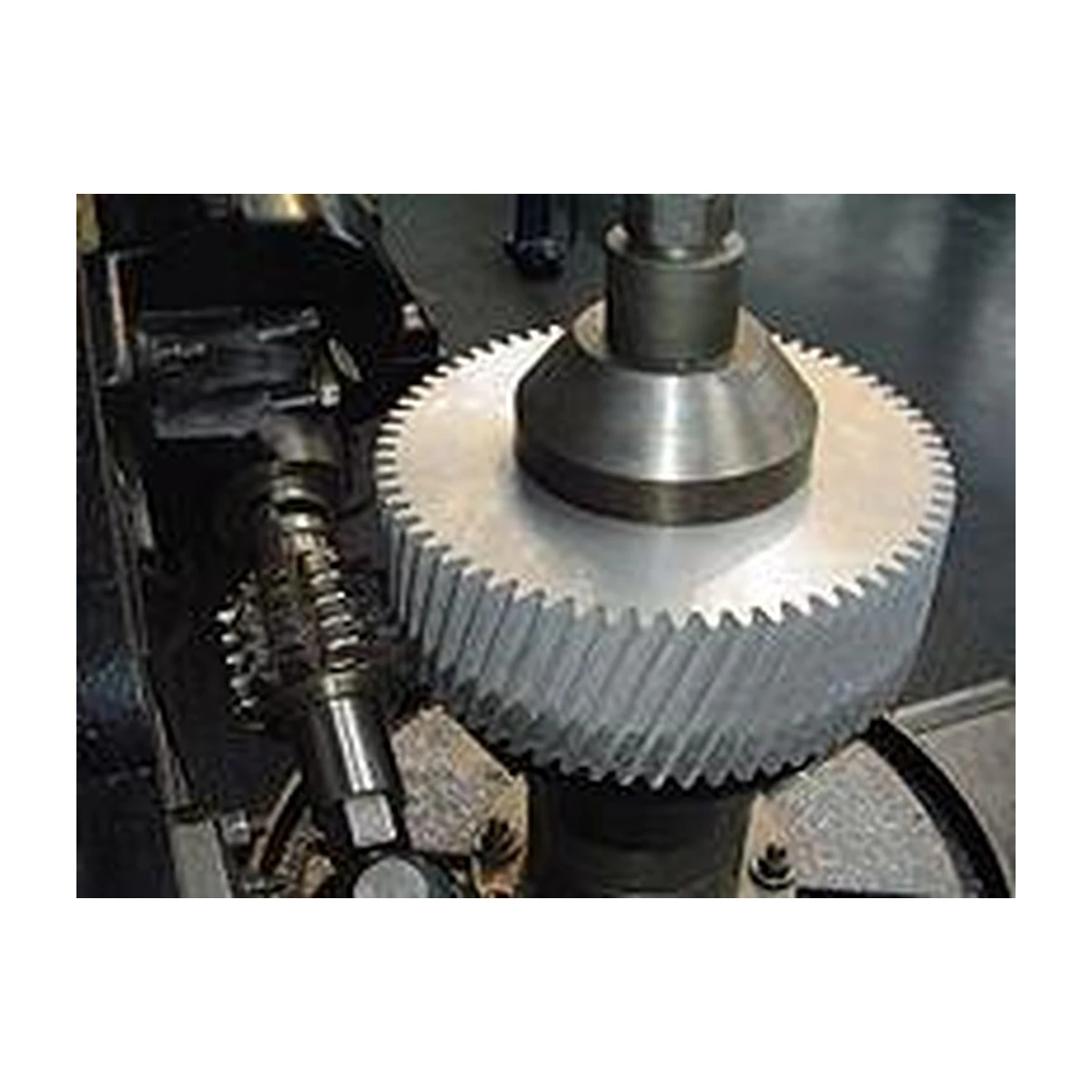
Large MC nylon gears may be bored and keyed like metal gears, but the polymer responds differently to clamping and environmental conditioning. Hub dimensions, keyway stress concentration and shaft fit should be chosen with the lower modulus and moisture response in mind.
Geometry and interface inputs for MC Nylon Gears
- MC nylon grade or material requirement
- Gear type, module/DP and tooth count
- Bore, keyway and hub dimensions
- Mating material and lubrication
- Moisture, temperature and load conditions
Geometry reference: Custom gear components including bevel configurations
Choosing the production route
Machining from cast nylon stock can support large diameters and lower production quantities without dedicated molding tooling. The stock condition, machining sequence and final conditioning state influence dimensions.
Packaged process reference: Machined configurations are documented; molding requires separate confirmation
Material direction: MC Nylon / nylon family
Application-specific design review
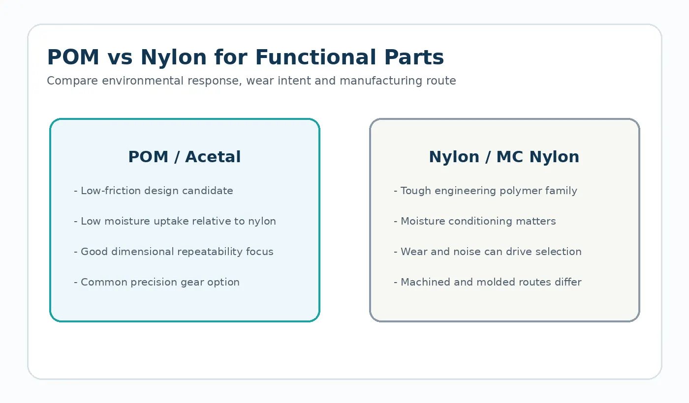
Moisture uptake and local clamping stress can change dimensions or runout. Thin sections may also distort during machining.
Typical use: Industrial machinery, conveyors and larger low-to-moderate speed gear applications where the selected nylon grade fits the duty. The final material and tolerance plan should be checked against the load path, mating components and environment in that assembly.
First sample and inspection focus
Specify the conditioning state and inspection temperature where fit is sensitive. Check bore, runout and tooth characteristics from the functional mounting datum.
Quotation decision: Humidity and conditioning, bore fit, mating material, load, speed, lubrication and allowable dimensional movement are important selection inputs.

What to send for a MC Nylon Gears quotation
Send the latest drawing or CAD model together with production quantity and the application conditions that affect fit, wear or dimensional stability. If the part replaces an existing component, identify the features that must remain interchangeable and any known field issue the new part is intended to solve.
- Controlled drawing revision and 3D model when available
- Mating-part or transmission geometry
- Material requirement or service environment
- Sample quantity, production batch and expected annual demand
- Critical dimensions and functional acceptance method