
Descrizione
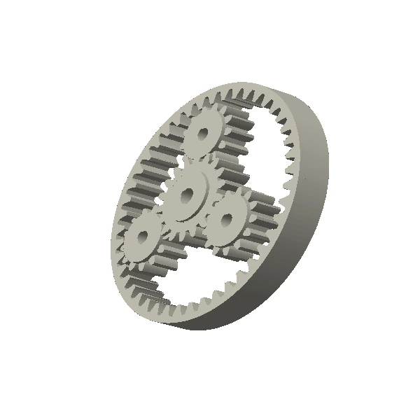
Sun, planet and ring gear components
Planetary gearing is a system of multiple simultaneous meshes. Tooth counts, carrier geometry, planet-pin positions and ring-gear concentricity must be mutually compatible before individual components are released.
Planetary sets require compatible tooth-count arithmetic and carrier geometry. If multiple planets are expected to share load, their pin positions and the ring reference must be controlled together. Integrated molded carriers can reduce part count, but they also put pin/bearing geometry into the molding tolerance stack.
How to read the product photograph
The main image is a photograph of a physical sample or representative component, not a dimensional definition. Resin colour, tooth count, bore or hub features, rack length, inserts and other details can change with the released drawing. Use the photograph to understand the product family; use the controlled drawing, mating interface and agreed inspection plan to manufacture and approve the part.
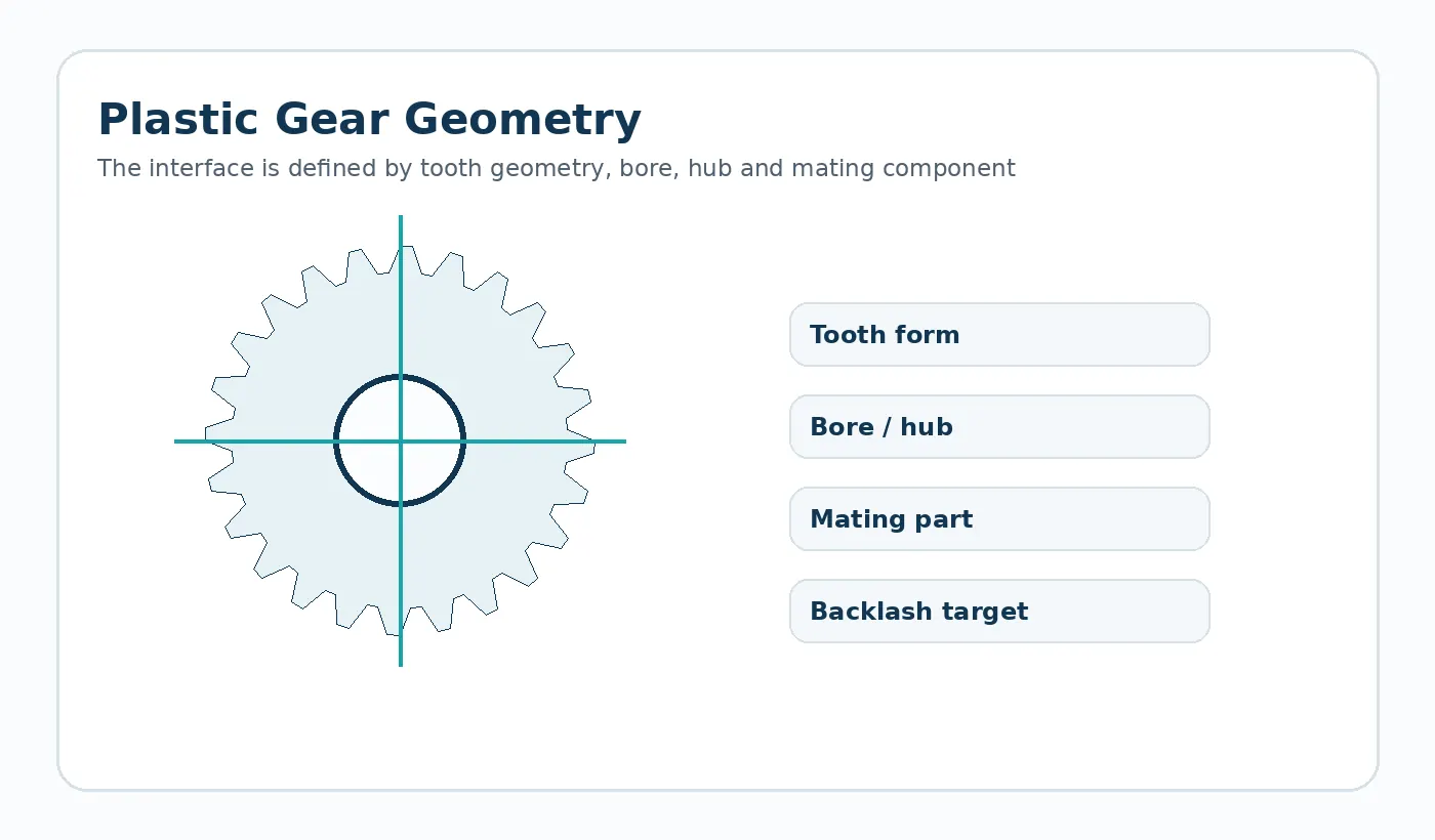
Geometry and interface inputs for Custom Injection Molded Planetary Gear Components
- Sun, planet and ring tooth counts
- Modulo/DP e angolo di pressione
- Planet quantity and carrier pin circle
- Bores, pin fits and ring mounting
- Phasing, backlash and torque path
Riferimento geometrico: Sun, planet, ring and related planetary components
Scelta del percorso produttivo
Molding can integrate gear and hub features for repeat volume, while machining may be preferred during development or for specific materials and sizes. The complete train should be reviewed before selecting a route.
Riferimento al processo di confezionamento: Injection molding for confirmed custom configurations
Direzione del materiale: Nylon or other selected engineering polymer after project review
Revisione della progettazione specifica dell'applicazione
Small pitch or position errors can accumulate across multiple planets. Carrier-pin location and ring distortion can therefore affect load sharing and noise.
Utilizzo tipico: Compact reducers, actuators, office mechanisms and electromechanical drives. The final material and tolerance plan should be checked against the load path, mating components and environment in that assembly.
Primo campione e focus dell'ispezione
Check gear geometry and the positional datums that locate the planets. Functional assembly tests may be appropriate when load sharing or noise is a critical requirement.
Decisione sul preventivo: Provide system ratio, tooth counts, module, ring/sun/planet relationship, carrier geometry, bore/shaft interfaces, speed, load and cycle requirements.
What to send for a Custom Injection Molded Planetary Gear Components quotation
Inviare il disegno o il modello CAD più recente, unitamente alla quantità di produzione e alle condizioni di applicazione che influiscono su montaggio, usura o stabilità dimensionale. Se il componente sostituisce un componente esistente, specificare le caratteristiche che devono rimanere intercambiabili e qualsiasi problema noto riscontrato sul campo che il nuovo componente intende risolvere.
- Revisione controllata del disegno e modello 3D, se disponibile.
- Geometria della parte di accoppiamento o della trasmissione
- Requisiti dei materiali o ambiente di servizio
- Quantità del campione, lotto di produzione e domanda annua prevista
- Dimensioni critiche e metodo di accettazione funzionale
Engineering specification to freeze before manufacture
A production drawing should convert the application into measurable inputs. The table below is the minimum review set for this product family; add any assembly-specific datum, finish or acceptance requirement that changes function.
| Definition | What the supplier needs |
|---|---|
| Sun tooth count | Show the value, tolerance or functional requirement on the latest drawing. |
| Planet tooth count | Show the value, tolerance or functional requirement on the latest drawing. |
| Ring tooth count | Show the value, tolerance or functional requirement on the latest drawing. |
| Module / pressure angle | Show the value, tolerance or functional requirement on the latest drawing. |
| Planet quantity and carrier pin locations | Show the value, tolerance or functional requirement on the latest drawing. |
| Ring mounting datum | Show the value, tolerance or functional requirement on the latest drawing. |
| Bore / shaft interfaces | Show the value, tolerance or functional requirement on the latest drawing. |
| Ratio, load, speed and backlash target | Show the value, tolerance or functional requirement on the latest drawing. |
Failure modes to prevent during design review
Common risks for this geometry include carrier pin position error; ring-to-sun eccentricity; unequal planet load sharing. These are best addressed before the first sample by reviewing the complete mating interface, not by tightening every drawing tolerance.
Use tolerances selectively. Dimensions that establish the tooth mesh, chain engagement, shaft fit or assembly datum deserve explicit measurement methods; non-critical molded surfaces can often use a more practical general tolerance.
First-article and production acceptance
Agree the inspection condition, datums and measuring method before sampling. The first-article report should cover the drawing CTQs and then be paired with a functional check in the real assembly or a representative fixture. For gears and sprockets, that can include mesh or chain engagement, runout and bore relationship; for custom molded parts it can include fit, fastening and loaded features.
Production control should follow the same CTQs rather than replacing them with a long list of easy-to-measure cosmetic dimensions. If a bore, tooth, insert or mounting surface is secondary-machined, make clear which operation establishes the final datum.
Engineering decision brief for Custom Injection Molded Planetary Gear Components
Define the geometry
Sun, planet, ring and related planetary components The quotation should use the drawing revision and mating interface as the controlling definition rather than an image alone.
Choose material by duty
Nylon or other selected engineering polymer after project review Material selection should be checked against load, speed, temperature, moisture or chemicals, lubrication and the required dimensional condition.
Freeze the production route
Injection molding for confirmed custom configurations The route should be fixed only after quantity, tolerances, surface requirements and change risk are understood.
Agree acceptance
Provide system ratio, tooth counts, module, ring/sun/planet relationship, carrier geometry, bore/shaft interfaces, speed, load and cycle requirements. First-article checks should therefore focus on the dimensions and functional interfaces that control the assembly.
Typical application context: Compact actuators, office equipment, appliances, robotics auxiliaries and custom motion systems.
Custom Injection Molded Planetary Gear Components FAQ
What should I send for quotation?
Send the latest 2D drawing and, where available, a 3D model. Add mating-part information, order quantity, service conditions and the features that control fit or motion. A sample is useful for replacement parts with uncertain legacy geometry.
How should the material be specified?
For POM or nylon projects, material family alone is not enough. Confirm the actual grade when it is mandatory, and state moisture, temperature, lubricant and mating material so dimensional and wear behavior can be reviewed.
How is the first sample approved?
Define the CTQs, inspection state and functional test before the sample is produced. Approval should confirm both measurable geometry and the behavior of the part in its intended interface.

























